Advertisement
Quick Links
Advertisement

Subscribe to Our Youtube Channel
Related Manuals for Duratuf MATAKANA


Summary of Contents for Duratuf MATAKANA
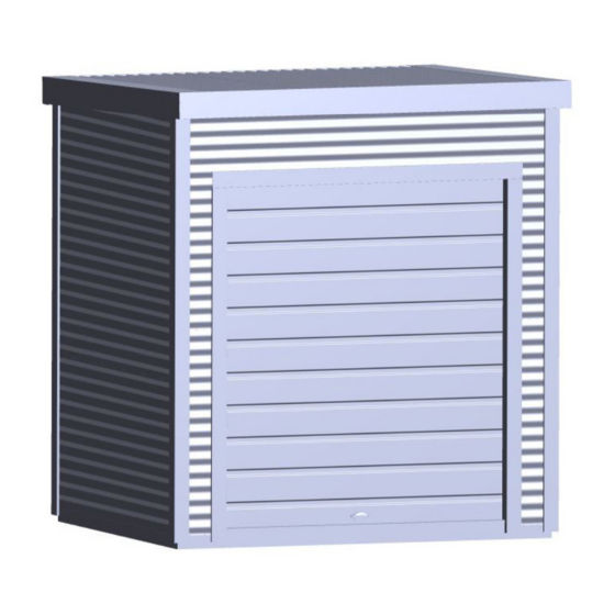
- Page 1 ASSEMBLY INSTRUCTIONS MATAKANA BASE SIZE: 2.400m x 2.000m...
- Page 2 • Protect your eyes and ears. • Use electric power tools with care. Use a Safety Trip Switch. • It is easier and quicker if this shed is assembled by two people. SOme understanding of building is recommended and there are some processes that require handyman experience. SELECT YOUR SITE • Your shed must be level. Achieve this by either levelling the ground or by using blocks. • If your shed is to be positioned on wet or damp ground, we recommend that your shed is raised up off the ground slightly. WARRANTY REQUIREMENTS The following maintenance process needs to be adhered to, to qualify for the steel warranty of your Duratuf Matakana shed. • Wash all surfaces annually using a hose and soft nylon brush. • Within 2 km of coast – wash every 3 months as above. After a storm, wash the cladding and the gutters as soon as possible to remove any highly corrosive salt deposits. • Volcanic Ash Fallout – wash as soon as possible, removing fall-out from roof and gutters. • Do not allow manures, chemicals or other corrosive materials to have direct contact with cladding.
- Page 3 PARTS LIST TIMBER FRAMING DESCRIPTION LENGTH DIAGRAM CHECKED Front/Back Base Plate 45 x 45 H4 (Green) 2.400m End Base Plate 45 x45 H4 (Green) 2.000m Front/Back Top Plate 45 x 45 H1 (Red) 2.400m End Top Plate 45 x 45 H1 (Red) 2.000m Lintel 45 x 45 H1 1.890m Stud 45 x 45 H1 (Yellow) 2.250m Stud 45 x 45 H1 (Yellow) 0.243m...
- Page 4 DESCRIPTION LENGTH PART# DIAGRAM CHECKED Front Corner Flashing 2.435m 1001 Back Corner Flashing 2.365m 1002 Door Top Flashing 1.995m 1003 Door Head Flashing 1.800m 1004 Door Jamb Flashing 2.032m 1005 Barge Flashing 2.395m 1006 Spouting 2.525m 1007 Downpipe Cover Flashing 2.240m 1008 Fascia 2.525m 1009 Front Top Plate Flashing 2.400m 1010 Spouting End Cap...
- Page 5 OPTIONAL EXTRAS CLEAR ROOF DESCRIPTION LENGTH DIAGRAM CHECKED Clear Roof Panel 2.330m PLY FLOOR DESCRIPTION LENGTH DIAGRAM CHECKED Plywood 17mm treated 2.400m x 1.000m Joists 70 x 45mm H4 2.310m Joists 70 x 45mm H4 2.000m Joists 70 x 45mm H4 0.444m Aluminium Door Step Flashing 1.795m Floor Screws 75mm Floor Screws 40mm Tek Screws 100mm SOLID TIMBER FLOOR KIT DESCRIPTION LENGTH DIAGRAM...
- Page 6 FOUNDATIONS • No doubt by now you will have decided what sort of flooring base you are going to use. • If you choose to pour a concrete floor, this is the best option as the cladding overlaps with the floor prevents the water from flowing inside the shed. Please see the details below for pouring your concrete floor. • The second option is to install your shed on a Duratuf Timber Floor Kit. If you have one of these floor kits, please make sure that you read through the instructions fully first and proceed to build this floor prior to starting your shed. You will need to ensure that the ground is firm and flat and the the floor is anchored down securely CONCRETE BASE BUILDING A CONCRETE SLAB FLOOR • Prior to to setting up the boxing for your concrete floor you will need to mark out the area to 300mm bigger than the size of the shed. Remove any soft soil or dirt, fill with sand or crusher dust and compact firmly to about 40-50mm below ground level. • The concrete base should be 100mm thick around the outside, 80mm in the middle and the top of the slab should be at least 50mm above the ground line to avoid water running into your shed. • Set up timber boxing to 2380mm x 1980mm (inside measurement of the boxing) This is 20mm smaller than the external measurement of the shed frame which allows a 10mm gap between the overhanging cladding and the concrete slab on all four sides of the shed.
- Page 7 TIMBER FRAME End Base Plates - 2 Front/Back Base Plates - 2 End Top plates - 2 Front/Back Top Plates - 2 Studs - 9 Nogs - 6 Lintel - 1 Front Roof Packer - 1 Centre Roof Beam - 1 TIMBER FRAME - BACK WALL Select: 1 x 2400mm Base Plate...
- Page 8 TIMBER FRAME - FRONT WALL Select 1 x 2400mm Base Plate 1 x 2400mm Top Plate 1 x 1890mm Lintel 4 x 2250mm Studs 2 x 1962mm Studs 4 x 243mm Jack Studs (short studs) 2 x 165mm Nogs • Lay out the top and bottom plates and the two outside studs, ensuring that the notches face outwards as shown. Nail together at the corners using two 75mm nails per corner. 1132mm Notches face outwards • Next take the remaining 2 studs (these are door studs). Use the 165mm nogs as spacers to position them 165mm in from the corner studs and nail them in place using 2 x 75mm nails top and...
- Page 9 ASSEMBLING THE TIMBER FRAME • Select 2 x 2000mm base plates (Green) and 2 x 2000mm top plates (Red). With the front wall lying on the ground, fit the notched out ends into the corresponding check outs in the front wall framing. • Ensure Green joins to Green and Red joins to Red and nail with 2 x 75mm nails. • Position the completed back wall frame on top of the 4 upright framing plates. • While someone supports the frame to ensure that it doesn’t move around, nail this back frame in place with 2 x 75mm nails at each corner.
- Page 10 ASSEMBLING THE TIMBER FRAME Centre Roof Beam • Position the Top Plate Packer on the top of the framing, flush with the front. This provides a 70mm slope for the roof. Top Plate Packer • Skew nail to the top plate using 8 x 75mm nails - 2 at each end and the rest evenly spaced. • Take the Centre Roof Beam and position over the 2 end wall studs and attach using 2 x 75mm nails at each end. • Select the Purlin Cleats and screw them under the centre roof beam and onto the centre end wall stud as shown using 4 x 40mm screws.
- Page 11 FLOORING - CONCTRETE SLAB If your shed has a concrete slab floor, position the frame onto the base. Note: if the shed floor is against a house or fence, you can position the shed after it has been built (but before you install the roller door). Please note that the design of the shed means that the wall cladding protrudes below the bottom of timber base plate.
- Page 12 FLOORING - TIMBER FLOOR KIT If your shed has an OPTIONAL TIMBER FLOOR KIT, fit this now. • Take all 5 x 2400mm Floor Joists and place them parallel (with 45mm face to the ground) as per the diagram. The outside joists are 2000mm apart and the centre 3 joists are 500mm spaces (to the centres). Joists • Select 2 x 2000mm floorboards and lay them on the top of the joists, one at each end as per the diagram. Nail the floorboards to the joists, flush at the corners, with 2 x 50mm flooring nails at each end. •...
- Page 13 FLOORING - PLYWOOD FLOOR KIT If your shed has an OPTIONAL PLYWOOD FLOOR KIT, fit this now. • Take the 5 x 2310mm long floor joists and lay them out parallel to each other on their short edges as shown (45mm face to the ground). Lay the 2 x 2000mm Joists across the ends. • Using 8 x 75mm screws, screw the outside joists together at the corners using 2 screws per corner. • Take 1 x 444mm Joist, and using it as a measuring packer, position the next internal joist at one end and fasten with 2 screws. Repeat at the other end. • Position and attached the other remaining 2 x joists the same way.
- Page 14 ATTACHING DPC TO FRAME Waterproofing is important to prevent leaks and keep the timber framing dry. Your shed has been supplied with a roll of DPC tape (Damp Proof Course) If your shed is positioned on a concrete or raised timber floor it is important that you should install the DPC before attaching the cladding to prevent water flowing between the base plate and floor.
- Page 15 ATTACHING THE DOOR HEAD FLASHING The door head flashing sits up underneath the lintel to cover the timber framing that would otherwise be exposed to the weather. • Select the door head flashing and position flashing on underneath and outside face of lintel. It should fit snugly between the door studs. • Holding the flashing in tight, nail it to the lintel using 6 x 30mm clouts, 3 x on the underside of the lintel and 3 on the front face of the flashing. Timber Lintel Door Head Flashing - ensure that the folded edge is under the lintel.
- Page 16 WALL CLADDING TO AVOID CORROSION: • Where at all possible try not to trap metal filings between two sheets. Remove all metal filings before riveting. • Carbon in pencils reacts with the Zinc/Aluminium coating on steel. Use an ink pen to mark the steel as required. CLADDING FIXING AND OVERLAP DETAIL WALL CLADDING FIXING PATTERN 25mm Tek Screws BASE PLATE FLOOR...
- Page 17 WALL CLADDING - BACK & ENDS Note - When attaching wall cladding, always ensure that the top sheet is flush with the top of the top timber framing plate and that the ends of the cladding sheets are flush and parallel with studs. This will ensure that wall panels are square. Always screw wall sheets through the trough (inner rib closest to the frame) of the profile. TOP WALL SHEET • Take a 2400mm length rear wall sheet and hold it in position at the top of the back wall. It must be flush with the top of top timber plate and both ends must be flush with the outside of the studs at either end. (Fig. 1) • Using 1 x 25mm tek screw, attach one end of the sheet to the frame at the top left hand corner of Fig.1 the sheet (Fig.1)(a). Place the screw approx 25mm in from end of the sheet (the corner flashing will cover the screws). • Repeat at the top of the sheet at the other end making sure that the cladding is flush with the top of the top plate. (Fig. 1) (b) NOTE: The middle sheet will need to lap UNDER the top sheet, so don’t screw right at the bottom of the sheet yet! The top sheet will finish 850mm below the top of the framing and the second sheet finisheds 1617mm down (see Wall Cladding Fixing Pattern on the previous page.
- Page 18 FIXING WALL CLADDING - FRONT The front wall cladding is attached the same way as the other side walls, except that the bottom cladding sheets either side of the roller door will overlap a lot more than the side and back walls. This will be explained in the step below “BOTTOM SHEET”. Steel flush with timber frame OVERDOOR CLADDING SHEET Fitting the top cladding sheet on the front wall will be a lot easier with 2 people and 2...
- Page 19 ATTACHING THE FLASHINGS Now it is time to finish the corners by fitting the Corner Flashings. PLEASE NOTE: Do NOT screw tek screws too tightly into the corner and door side flashings as they will pull in and leave a dent. We will screw the corner flashings onto each corner using 6 x 55mm tek screws per corner, 3 x into each face of the flashing, 2 x at the top, 2 x at the bottom and 2 x in the middle. The top screws should be approx 250mm down from top of top...
- Page 20 FITTING THE SPOUTING This shed comes with a built in spouting and downpipe system so that you can easily manage the water runoff. CUTTING THE DROPPER HOLE • Preparation for fitting the end caps, you will need to cut out the hole for the 200mm downpipe dropper. • Determine which end you want the downpipe and mark a line 200mm in from the end of the spouting as per the diagram on the right. You will be cutting a 80mm hole in the centre of the base of the spouting. • Place a mark in the centre of your 200mm line, and using this as the centre, scribe a mark with a diameter of 80mm. 80mm • Cut out the hole by drilling a few small holes then using tin snips to enlarge to the correct size.
- Page 21 FITTING THE DOWNPIPE FITTING THE DOWNPIPE • Silicone the lip of the dropper that will be in contact with the spouting. Place it in the hole. Make sure it is straight. Add extra silicone as required for a watertight seal. Allow the silicone to dry. • Measure and cut the downpipe to the right length, push it up tight and secure tightly by using one rivet through into the dropper and riveting the two brackets to rear wall cladding. • Position the downpipe cover flashing over downpipe and rivet to wall cladding using 6 rivets. FITTING THE FRONT TOP PLATE FLASHING • The Front Top Plate Flashing sits on the top plate and comes down the front of the shed over the top of the front wall cladding. The folded edge of the flashing is on the front part of the flashing.
- Page 22 ROOF If an optional clear roof sheet has been supplied, this can be fitted in any of the middle positions. (Note - both edges of clear roof sheet overlap the steel sheets at each side vs the steel sheets that are under on one edge and over on the other).
- Page 23 FASCIA, SPOUTING & BARGE • Select the left hand barge flashing. This will fit in between the fascia and the back spouting. We will be attaching the barges to the spouting at the back first and fitting the fascia last. Barge Flashing • Hold the flashing in firmly against the side of the shed spanning over the roof corrugate and down the side of the shed. • Line the end of the barge up with the back of the spouting. The barge should fit over the top and bottom of the spouting. Drill a 3.5mm hole into the top of the spouting in the corner and fix 2 x rivets.
- Page 24 ROLLER DOOR BEFORE YOU BEGIN • This Roll-A-Door is designed and tested to provide security, attractive appearance and smooth, low effort operation provided it is installed and operated in strict accordance with the following safety warnings. Failure to comply with the following instructions may result in death, serious personal injury or property damage. • NOTE: Do not unwrap packaging around roller door until requested, as this will untension the door. SERIES 1 ROLL-A-DOOR DESCRIPTION ITEM PACKED CHECKED Rolled plastic wrapped door “A” Style brackets, left & right hand side Door guides, left & right hand side Steel locking bars SMALL PARTS BAG CONTAINING: Guide clips (door size dependent) 4-10 Door handle and fixing to suit Bottom rail stops and 6mm screws Faceplate and lock assembly (2 keys) Locking bar retainer Locking bar covers...
- Page 25 ROLLER DOOR PARTS CHECKLIST REQUIREMENTS BEFORE INSTALLATION • Level and plumb - The door must be installed in an absolutely level position, if opening is not level and square, appearance and/or sideroom requirements will be affected. The floor should be level or recessed across the opening to avoid gaps. MEASUREMENTS • Opening width - As the standard door overlaps each side by 30mm or more, the door should be 60mm wider than the 1800mm opening. • Opening height - The door opening height (or drive through clearance) indicates the distance between the ground and rubber seal at the bottom of the door, with door fully open. For doors with a handle, the bottom rail is recommended to hang a minimum of 80mm below the lintel. OPENING WIDTH LINTEL HEIGHT...
- Page 26 ROLLER DOOR LINTEL HEIGHT DRIVE THROUGH CLEARANCE DRIVE THROUGH CLEARANCE for doods with handle HEADROOM REQUIREMENTS FOR DOORS • Headroom - A minimum of 410mm of headroom is required. If the door is installed lower into the opening than shown below, additional loss of door opening height will result. RECOMMENDED HEADROOM Required for door with handle...
- Page 27 ROLLER DOOR INSTALL FIRST BRACKET • Measure the door curtain width and mark where edge of curtain will be, allowing for over lap on each side of the opening. • Add clearance of 20-30mm from edge of curtain to inside edge of bracket to determine positioning of the bracket. • Headroom. Measure up 120mm from underside of the lintel. • Mark two hole positions using top and bottom slots on the bracket. • Drill both holes, then attach bracket using the 50mm x 10mm coach screws and washers supplied. 120mm Line for edge of door 20-30mm INSTALL SECOND BRACKET Water Level •...
- Page 28 ROLLER DOOR centering axle WARNING! practice correct lifting techniques axle “floats” in either direction POSITION DOOR BOTTOM RAIL AT 3 O’CLOCK • Centre the door with the opening, while ensuring the floating axle is also centred with the door. Do this by lining up previous marks with the hub,then lift both the axle and the door together until it is centred with the opening. • Rotate the curtain and axle so that the bottom rail of the door is positioned as shown (3 o’clock). • Push the axle forward in the slots (toward the opening) and tighten the nuts firmly without overtightening.
- Page 29 ROLLER DOOR ATTACHING STOP To attach bottom rail stops (G) to bottom rail of door. • Hook stop behind lip in rail, as shown. • Secure from underneath the rail with screws (G) supplied. Trim the weatherseal flush with the end of the bottom rail. stop GUIDES • Check that curtain overlaps equally on both sides, and cut the guides (C) to the correct length that is, level with the brackets (B roll-a-guide bottom rail lip • Slide four guide clips (E) into each guide (C). Position the bottom clip 200mm from the floor with the rest evenly spaced along the guide. bottom To prevent clips from sliding down the guide, temporarily rail secure them with adhesive tape. •...
- Page 30 ROLLER DOOR FITTING HANDLE • Fit the handle (F) to the outside of the door using the screws (P), nuts and washers provided CENTRE LIFT LOCK LACERATION Wear appropriate gloves as some edges of the door are very sharp. • Raise the curtain until the lock corrugation is visible above the door guides. Legs • Install locking bar retainer (I) in line with lock corrugation by pushing retainer towards door edge, sliding the legs under the Nylofelt®...
- Page 31 ROLLER DOOR Faceplate Lock Lock bar cover assembly Double sided adhesive tape WARNING: Locking bar covers must be installed to prevent Lock bar cover possible finger entrapment. CLEAN UP • Remove all swarf (drill filings) with a soft brush or rag. • Hose down roof and walls thoroughly. • For Coloursteel sheds use touch-up paint provided on all nail heads, rivets and exposed cuts.
- Page 32 ROLLER DOOR TROUBLESHOOTING SYMPTOM POSSIBLE CAUSE REMEDY Door is hard to Door jamming in the guides Check: operate in ANY a) the guide clearances DIRECTION b) the guides are plumb c) that the guide surfaces are clean and free from oil d) that the locking bars are the correct length e) that the weatherseal is correct length The door is hard The spring tension requires a) If the door is hard to lift, but tends to drop, refer to section to operate in ONE...
- Page 33 ROLLER DOOR ADJUST TO SPRING TENSION WARNING: Ensure that pipe wrench is fitted correctly to the axle and if it is gripped onto the axle do not underestimate the tension in the spring when undoing the clamps. CAUTION: THIS ADJUSTMENT REQUIRES 2 PERSONS TO COMPLETE. a) With the door rolled up tie two ropes around the door roll approximately 300mm from each end, as a safety precaution. b) With a person at each end of the door, hold the axle firmly with a large pipe wrench (Stillson) at TO LOOSEN least 450mm long. SPRING TENSION c) Loosen the “U” bolt nuts at both ends and KEEP A FIRM GRIP ON WRENCH. d) Rotate the axle in the required direction (see diagram).
- Page 34 ROLLER DOOR We suggest you record your full Key letter and Number on the front of this manual and if replacement keys are required they can be obtained from your nearest B&D office, simply by quoting this number. If the keys have been lost and the number not recorded, it can be found stamped into the locking arm at the back of the mechanism. NYLOFELT® On no account should you use grease or oil in the door guides or on the Nylofelt® running strips – the grease or oil will clog the Nylofelt® and spoil the operation of the door. An occasional wipe with a cloth dampened with mineral turps or methylated spirits, down the inside of each guide, is very beneficial in removing any trace of grease or dirt. After the guides have been cleaned, a silicon spray may be used in the guides. NOTE: WD40 or similar oil based sprays are not silicon and should not be used. Care should be taken not to damage the Nylofelt®, however, if Nylofelt® is cut or damaged, a lighted match should be used to quickly seal the ends of the nylon braiding, so as to stop any further deterioration. Regular maintenance required B&D recommends that you check the operation of your Roll-A-Door® at least every six months (more regularly in extreme environments or frequent use). The effort required to manually open and to manually close the door should be about the same (if door has an automatic opener, put into manual mode before testing door). If the door is difficult to operate in either direction (up or down) then check: 1) that the Nylofelt® running strips on each side of the door have not slipped from the edge and are jamming the door; 2) that the door is running correctly in the guides and the guides are straight and perpendicular; and 3) that the inside surfaces of the guides are clean and free of obstructions. (see paragraph on care of Nylofelt®) If you have checked these (and corrected where necessary) and the door is still difficult to operate, then your door will need a service to adjust the spring tension and possibly other operational parts of the door. This service should only be carried out by an experienced door technician, using the correct tools. If you have an automatic opener fitted to your door, it is particularly important that you ensure the optimum operation of the door, otherwise you may reduce the effective life of the opener. To keep your door running well, it is recommended that your door be serviced, by an experienced door technician, every 12 months (more regularly in extreme environments or frequent use), or earlier if required. Spring tension It is natural for springs to lose tension over time. When spring tension is adjusted or when your door is first installed it is usual to apply a little more tension than is required for balanced operation, to allow for the normal “settling in” of the springs.
- Page 35 The structural framing and cladding warranties are subject to the shed being installed on a level concrete base, or other solid supports, at least 40mm above ground level, and contact being prevented at all times with soil, vegetation, organic matter, fertilizers, or other moisture retaining substances. • In the rare event of a claim and upon receiving proof of purchase and defect, Duratuf will at its option repair or replace defective parts, or provide a prorated refund for the remaining life of the applicable warranty. Any replacement product provided will be covered by the Warranty for the balance of the Warranty term as if the replaced product were the original product. • Duratuf reserves the right to inspect the shed in situ at the installation site and to conduct tests at any time after a Warranty claim is received. Any interference with the shed prior to inspection by Duratuf may void a claim under this Warranty. • Any product replaced under this Warranty becomes the property of Duratuf. • Any failure, delay, or indulgence by Duratuf will not operate as a waiver. A waiver by Duratuf of any condition of this Warranty is not a waiver of any other condition. No waiver is effective unless it is in writing. • All terms, conditions, warranties, undertakings, inducements, and representations other than contained in this warranty, whether express or implied, statutory, or otherwise, are expressly excluded.
Need help?
Do you have a question about the MATAKANA and is the answer not in the manual?
Questions and answers