Table of Contents
Advertisement
Quick Links
Advertisement
Table of Contents

Subscribe to Our Youtube Channel
Related Manuals for Duratuf KAIPARA


Summary of Contents for Duratuf KAIPARA
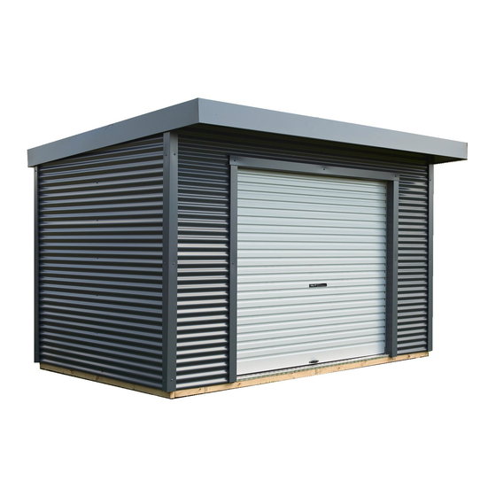
- Page 1 ASSEMBLY INSTRUCTIONS KAIPARA BASE SIZE: 3.900m x 2.550m...
-
Page 2: Tools Required
• If your shed is to be positioned on wet or damp ground, we recommend that your shed is raised up off the ground slightly. WARRANTY REQUIREMENTS The following maintenance process needs to be adhered to, to qualify for the steel warranty of your Duratuf Guardian shed. • Wash all surfaces annually using a hose and soft nylon brush. • Within 2 km of coast – wash every 3 months as above. After a storm, wash the cladding and the gutters as soon as possible to remove any highly corrosive salt deposits. -
Page 3: Parts List
PARTS LIST TIMBER DESCRIPTION LENGTH DIAGRAM CHECKED Front/Back Base Plate 70 x 45 H4 (Green) 3.900m End Base Plate 70 x45 H4 (Green) 2.410m Front/Back Top Plate 70 x 45 H1 (Red) 3.900m EndTop Plate 70 x 45 H1 (Red) 2.410m Lintel 70 x 45 2.400m... - Page 4 DESCRIPTION LENGTH PART# DIAGRAM CHECKED Front Top Plate Flashing 3.900m 1001 Front Corner Flashing 2.540m 1002 Rear Corner Flashing 2.400m 1003 Door Top Flashing 2.590m 1004 Door Head Flashing 2.400m 1005 Door Jamb Flashing 2.105m 1006 Downpipe Cover Flashing 2.200m 1007 Barge Flashing 3.225m...
-
Page 5: Optional Extras
OPTIONAL EXTRAS TIMBER FLOOR DESCRIPTION LENGTH DIAGRAM CHECKED Floor Joists 100 x 50 H4 3.880m Floor Boards 150 x 25 H3 2.530m Door Step Flashing 2.400m Floor Nails 50mm CLEAR ROOF DESCRIPTION LENGTH DIAGRAM CHECKED Clear Roof Panel 3.150m PLY FLOOR DESCRIPTION LENGTH DIAGRAM... -
Page 6: Concrete Base
FOUNDATIONS • No doubt by now you will have decided what sort of base you are putting down. • If you choose a raised foundation, either a concrete base, plywood fl oor, or timber fl oor, the shed design prevents the water from fl owing inside the shed. • If you chose to position the shed directly onto the ground, the water can fl ow down the walls and under the bottom plate and into the shed. - Page 7 PLYWOOD FLOOR Select SUB FLOOR FRAME 6 x 3790mm Joists 3790mm 2 x 2530mm Joists 1 x 532mm Joists 1 x 63mm Joists 3 x 555mm Joists 532mm 4 x Ply 1945mm x 1200mm 2 x Ply 1945mm x 130mm 555mm • Layout fl oor joists and assemble sub fl oor frame as shown, nailing joists together...
- Page 8 TIMBER FLOOR SUB FLOOR FRAME Select 6 x 3880mm Joists 3880mm 26 x 2530mm Floor boards • Layout fl oor joists as shown, ensuring joists are spaced evenly apart. • Using 50mm fl ooring nails, nail a fl oor board on each end, ensuring ends are fl ush with joists. Make sure fl oor is level and joists are well supported.
- Page 9 TIMBER FRAME End Base Plates - 2 Front/Back Base Plates - 2 End Top plates - 2 Front/Back Top Plates - 2 Studs - 19 Ridge beam - 1 Nogs - 9 Lintel - 1 TIMBER FRAME - END WALLS Select 2 x 2410mm Base Plates 2 x 2410mm Top Plates...
- Page 10 TIMBER FRAME - BACK WALL Select 1 x 3900mm Base Plate 1 x 3900mm Top Plate 4 x 2295mm Studs 3 x 1240mm Nogs • Select one 3900mm base plate (Green), one 3900mm top plate (Red) and four studs (Yellow). •...
- Page 11 TIMBER FRAME - ASSEMBLE FRAME • Stand up back wall frame and one end wall frame. • Using a 10mm drill, predrill and screw both frames together using four 100mm tek screws per corner. (100mm down from top and 100mm up from base and remaining screws evenly spaced in between.) • Ensure end wall panels fi t in between front and back frames.
- Page 12 ATTACHING DPC TO FRAME • Any shed that has a fl oor should have the DPC attached to prevent water fl owing between bottom plate and fl oor. • Using approx forty 30mm clouts, nail DPC to bottom plate ensuring top is fl ush with top of base plate. • Note if the shed doesnt have a fl oor, and is positioned directly WALL CLADDING on the ground, you wont need to attached DPC on the base plate.
- Page 13 WALL CLADDING TO AVOID CORROSION: • Where at all possible try not to trap metal fi lings between two sheets. Remove all metal fi lings before riveting. • Carbon in pencils reacts with the Zinc/ Aluminium coating on steel. Use ink to mark steel. CLADDING DETAIL CLADDING DETAIL Side View Overlap...
- Page 14 WALL CLADDING - BACK & ENDS • Note - When attaching wall cladding always ensure • Note - When attaching wall cladding always ensure top sheet is level with top plate and ends of sheet are fl ush and parallel with studs. This will ensure that are fl ush and parallel with studs. This will ensure that wall panels are square.
- Page 15 FLASHINGS FLASHINGS • Centralise front top plate fl ashing on top of top plate • Centralise front top plate fl ashing on top of top plate and attach fl ashing with four 30mm clouts to top plate. • Screw corner fl ashings onto each corner, using six 55mm tek screws per corner. Top screws should be approx 250mm down from top of top plate. • Ensure corner fl ashings are square and parallel with walls panels.and top of fl ashings are level with top of top plate.
- Page 16 BACK SPOUTING • Using six rivets per end, fi t and rivet end caps to each end of back spouting. • Determine position of downpipe and cut hole in underside of spouting. (Note - hole needs to be at least 300mm or more from end of spouting, and slightly smaller than plastic dropper supplied.) •...
- Page 17 ROOF • If an optional clear roof sheet has been supplied, this • If an optional clear roof sheet has been supplied, this can be fi tted in any of the middle positions. (Note can be fi tted in any of the middle positions. (Note - both edges of clear roof sheet overlap standard - both edges of clear roof sheet overlap standard sheets at each side.) • Position fi rst roof sheet into position ensuring sheet • Position fi rst roof sheet into position ensuring sheet...
- Page 18 SPOUTING & BARGE • Position front spouting onto front of roof sheets. • Using 15 rivets (3 per sheet), rivet spouting to the ribs on roof sheets. • Using tin snips, trim 25mm off bottom fold from front spouting to allow barge to fi t into front spouting. Using tin snips, trim 100mm off bottom fold at the rear of both barges, to allow barge to fi t into rear spouting. It is...
-
Page 19: Before You Begin
ROLLER DOOR BEFORE YOU BEGIN • This Roll-A-Door is designed and tested to provide security, attractive appearance and smooth, low eff ort operation provided it is installed and operated in strict accordance with the following safety warnings. Failure to comply with the following instructions may result in death, serious personal injury or property damage. -
Page 20: Parts Checklist
ROLLER DOOR PARTS CHECKLIST REQUIREMENTS BEFORE INSTALLATION • Level and plumb - The door must be installed in an absolutely level position, if opening is not level and square, appearance and/or sideroom requirements will be aff ected. The fl oor should be level or recessed across the opening to avoid gaps. MEASUREMENTS •... - Page 21 ROLLER DOOR LINTEL HEIGHT DRIVE THROUGH CLEARANCE DRIVE THROUGH CLEARANCE for doods with handle HEADROOM REQUIREMENTS FOR DOORS • Headroom - A minimum of 410mm of headroom is required. If the door is installed lower into the opening than shown below, additional loss of door opening height will result. RECOMMENDED HEADROOM Required for door with handle...
- Page 22 ROLLER DOOR INSTALL FIRST BRACKET • Measure the door curtain width and mark where edge of curtain will be, allowing for over lap on each side of the opening. • Add clearance of 20-30mm from edge of curtain to inside edge of bracket to determine positioning of the bracket.
-
Page 23: Position Door
ROLLER DOOR centering axle WARNING! practice axle “fl oats” in correct lifting techniques either direction POSITION DOOR BOTTOM RAIL AT 3 O’CLOCK • Centre the door with the opening, while ensuring the fl oating axle is also centred with the door. Do this by lining up previous marks with the hub,then lift both the axle and the door together until it is centred with the opening. -
Page 24: Attaching Stop
ROLLER DOOR ATTACHING STOP To attach bottom rail stops (G) to bottom rail of door. • Hook stop behind lip in rail, as shown. stop • Secure from underneath the rail with screws (G) supplied. Trim the weatherseal fl ush with the end of the bottom rail. GUIDES roll-a-guide bottom rail lip •... -
Page 25: Fitting Handle
ROLLER DOOR FITTING HANDLE • Fit the handle (F) to the outside of the door using the screws (P), nuts and washers provided CENTRE LIFT LOCK LACERATION Wear appropriate gloves as some edges of the door are very sharp. • Raise the curtain until the lock corrugation is visible Legs above the door guides. - Page 26 ROLLER DOOR Faceplate Lock Lock bar cover assembly Double sided adhesive tape WARNING: Locking bar covers must Lock bar cover be installed to prevent possible fi nger entrapment. CLEAN UP • Remove all swarf (drill fi lings) with a soft brush or rag. • Hose down roof and walls thoroughly. • For Coloursteel sheds use touch-up paint provided on all nail heads, rivets and exposed cuts.
-
Page 27: Troubleshooting
ROLLER DOOR TROUBLESHOOTING SYMPTOM POSSIBLE CAUSE REMEDY Door is hard to Door jamming in the Check: operate in ANY guides a) the guide clearances DIRECTION b) the guides are plumb c) that the guide surfaces are clean and free from oil d) that the locking bars are the correct length e) that the weatherseal is correct length The door is hard... -
Page 28: After Installation Care
ROLLER DOOR ADJUST TO SPRING TENSION WARNING: Ensure that pipe wrench is fi tted correctly to the axle and if it is gripped onto the axle do not underestimate the tension in the spring when undoing the clamps. CAUTION: THIS ADJUSTMENT REQUIRES 2 PERSONS TO COMPLETE. a) With the door rolled up tie two ropes around the door roll approximately 300mm from each end, as TO LOOSEN a safety precaution. - Page 29 ROLLER DOOR We suggest you record your full Key letter and Number on the front of this manual and if replacement keys are required they can be obtained from your nearest B&D office, simply by quoting this number. If the keys have been lost and the number not recorded, it can be found stamped into the locking arm at the back of the mechanism.
-
Page 30: Warranty Registration
DURATUF PREMIUM SHED WARRANTY GUARANTEE TO CUSTOMER Congratulations on purchasing a Duratuf Storage Shed. With proper care and attention, this product will last any years. For your benefi t PLEASE READ THE FOLLOWING INFORMATION CAREFULLY. WARRANTY ON METAL CLADDING Riverlea Group Ltd guarantee that the metal roofi ng and wall cladding on Kiwi and Fortress Garden Sheds may be used in moderate and inland corrosion zones or areas where the fi rst year mild steel corrosion rate is less than 200g/m2, and that in these conditions, they will not perforate due to corrosion within 18 years of date of manufacture.
Need help?
Do you have a question about the KAIPARA and is the answer not in the manual?
Questions and answers