Table of Contents
Advertisement
Quick Links
Advertisement
Chapters
Table of Contents

Subscribe to Our Youtube Channel
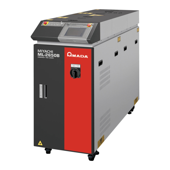
Related Manuals for Amada ML-2650B


Summary of Contents for Amada ML-2650B
- Page 1 YAG LASER WELDER ML-2650B/2651B OPERATION MANUAL AA06M0666E-34...
-
Page 2: How To Use This Document
In this manual, ML-2650B denotes ML-2650B, ML-2650B-CDRH, and ML-2651B denotes ML-2651B, ML-2651B-CDRH. Thank you for purchasing our YAG Laser Welder ML-2650B/2651B. This operation manual explains its method of operation and precautions for use. Before using, read this operation manual carefully; after reading, save it in a proper place for your future reference. -
Page 3: Table Of Contents
3. Functions of the ML-2650B/2651B ........ - Page 4 Setting Equipment No......... .147 ML-2650B/2651B...
- Page 5 Specifications ............203 ML-2650B/2651B...
- Page 6 Index ............225 ML-2650B/2651B...
-
Page 7: For Use In Safety
Both direct laser beams and scattered laser beams are highly dangerous. If the beam enters the eye directly, it can cause blindness. Never burn, destroy, cut, crush or chemically decompose the Laser. This product incorporates parts containing gallium arsenide (GaAs). ML-2650B/2651B... - Page 8 Those who use a pacemaker must not approach the Laser or walk around the welding shop while the Laser is in operation, without being permitted by his/her medical doctor. The Laser generates a magnetic field and has effects on the operation of the pacemaker while it is turned ON. ML-2650B/2651B...
- Page 9 Surface flash and expulsion can burn the skin if they touch the skin. Keep a fire extinguisher nearby. Keep a fire extinguisher in the processing shop in case of fire. Maintain and inspect the Laser periodically. Maintain and inspect the Laser periodically, and repair any damage before starting operation. ML-2650B/2651B...
-
Page 10: Precautions For Handling
* MPE: The maximum level of permissible exposure of the eyes or skin to laser beams. Abbreviation of Maximum Permissible Exposure. * For other information on managing laser equipment or the MPE level, refer to the following standards. CDRH Standards Part 1040 Sec. 1040.10 “Radiation safety standards for laser equipment” ML-2650B/2651B... -
Page 11: For Transportation
⇒ When transporting, belt the Laser to fix and keep it horizontal. Adjuster Adjuster Fork Fork 850 mm or more Figures below show example forking; insert the forks fully till the points appear from under the Laser. DON'T ML-2650B/2651B... - Page 12 1.5 times the Laser width including the cushion. When the belt is not long enough as shown, insert a board (plywood, angle plate, etc.) on the Laser not to hurt the top surface of the Laser. ML-2650B/2651B...
- Page 13 Laser. ⇒ Insert pillows such as timber between the bottom of the Laser and floor to balance the Laser. For positioning the pillows, refer to that for the forks of lift truck. Pillows Floor ML-2650B/2651B...
- Page 14 * The wall in the above Figures may be replaced with a plank or rod as far as it can support the Laser. ⇒ When it is expected that the Laser may bounce during transportation, belt the Laser longitudinally. ML-2650B/2651B...
-
Page 15: For Disposal
Precautions for Handling For Disposal This product incorporates parts containing gallium arsenide (GaAs). At the time of disposal, separate it from general industrial waste or domestic waste and carry out the disposal in accordance with applicable laws and regulations. ML-2650B/2651B... -
Page 16: Sticking Warning/Danger Labels
P-00374-001 注 意 CAUTION 継手からホースを外す場合や、電磁弁のフィルタを掃除する際は、 水が飛び散らないようご注意ください。 水が通風孔などから装置内部に入ると、故障の原因となります。 MANUFACTURED BY: AMADA WELD TECH CO.,LTD. WHEN DISCONNECTING HOSE FROM JOINT OR 95-3 FUTATSUKA NODA-CITY CLEANING SOLENOID VALVE FILTER, TAKE CARE CHIBA 278-0016 JAPAN NOT TO SPLASH WATER. IF WATER ENTERS THE EQUIPMENT THROUGH VENTS, IT MAY CAUSE TROUBLE. - Page 17 開口からレーザ放射が出る。 P-00377-001 注 意 BELT 荷上げベルトは、左図のように キャスターとアジャスターの間に HERE 通して下さい。 MANUFACTURED BY: AMADA WELD TECH CO.,LTD. CAUTION 95-3 FUTATSUKA NODA-CITY CHIBA 278-0016 JAPAN BELT BETWEEN CASTERS MODEL No. AND ADJUSTERS AS SHOWN. SERIAL No. LABEL P-00027-001 (Also stuck on the reverse side)
- Page 18 T U R N C L O C K W I S E T O S E C U R E T H E F I B E R O P T I C . GROOVE P-1212 Inside of the top surface of the main unit (top surface of the branch unit cover) Inside of the front surface of the main unit (front surface of the cooling water tank) ML-2650B/2651B...
-
Page 21: Chapter 1 Overview Of The Yag Laser Welder
When the output unit is provided with a CCD camera, cross lines are generally displayed on the monitor and the cross point of these cross lines is an irradiation point. In this laser, a red point appears on the workpiece when guide light is output. ML-2650B/2651B... -
Page 22: Mechanism Of The Yag Laser
3 optical fibers. Up to 4 deliveries are available for this laser equipment at timesharing. Common Laser Equipment Configuration Oscillator Power monitor Optical fiber YAG rod Input unit Mirror Output unit Excitation lamp Workpiece Power supply Cooler Beamsplitter Example of 3 deliveries ML-2650B/2651B... -
Page 23: Functions Of The Ml-2650B/2651B
3. Functions of the ML-2650B/2651B 3. Functions of the ML-2650B/2651B ⇒ Laser power feedback control and optional waveform control functions ■ The Laser can handle a wide variety of workpieces. Up to 32 different settings for weld schedules using waveform control are available. -
Page 24: Product Composition
Approx. 13.5 kg Checking the Packaged Products Make sure that all the packaged products are included. Package for main unit Product name Model No. Q’ty YAG Laser Welder ML-2650B/2651B Package for accessories Product name Model No. Q’ty Flashlamp MLD-0602 Flowtube for lamp... - Page 25 Main Unit, Optical Fiber, and Output Unit This product is used in combination with the optical fiber and output unit as shown below. Optical fiber x Output unit x Main unit x 1 Number of deliveries Number of deliveries Main unit Output unit Optical fiber ML-2650B/2651B...
- Page 26 For details, refer to the Appendixes, "Specifications" on page 204. Output unit The output unit with the specification that you selected at the time of purchase is connected to the main unit. For details, refer to the Operation Manual or Specification for the output unit. ML-2650B/2651B...
-
Page 27: Options
For the maintenance parts separately sold, refer to the Maintenance Part, Chapter 1 "1. Maintenance Parts and Standard Intervals of Inspection/ Replacement" on page 173. Fiber Scope This fiber scope is used to check the incident status to the optical fiber. Purchase it as required. P10× ML-2650B/2651B... - Page 28 When the printer (BL2-58SNWJC: SANEI ELECTRIC INC.) is connected by RS-485 cable, the output schedules of each schedule and measured values on the monitor screen can be printed out. Purchase the printer as required. Top side Rear side IF connector ML-2650B/2651B...
-
Page 29: Chapter 2 Name And Functions Of Each Section
For viewing the cooling water level in the cooling water tank. Windows (4) Front Door Handle Used to open the front door. Press the button under the handle and the handle will pop out. After closing the door, put back the handle into place and the door will lock. ML-2650B/2651B... -
Page 30: Inside Of The Front Side
When viewing the waveform of laser output, Connector connect to an oscilloscope. (5) RS-485 (1) Connects a personal computer or printer to use the external communication Connector function. (6) RS-485 (2) Connects a personal computer or printer to use the external communication Connector function. ML-2650B/2651B... - Page 31 Shows proper level of the secondary cooling water. Label (10) Ion-Exchanger Increases purity of the secondary cooling water. (11) Water Filter Removes fur and other contaminants from secondary cooling water. (12) Drains For draining water in the piping to prevent freeze. ML-2650B/2651B...
-
Page 32: Name And Function Of Each Section On The Top Side
(5) Head Cover A, B This is a cover for the laser oscillator section. (6) Laser Controller This controller sets welding conditions and operates the laser welder. Setting items and set values are displayed on the touch panel type liquid crystal display. ML-2650B/2651B... -
Page 33: Laser Controller (Mle-122A)
The laser controller is accommodated in the control panel on the top surface of the main unit and used to set welding conditions and performs operations to output laser light. If the laser controller is dismounted from the main unit, operations can be performed in a place remote from the laser welder. ML-2650B/2651B... -
Page 34: Laser Oscillator Section
Status where the top cover is open Status where the branch unit cover is removed (7) (6)(5) (4) (3) (10) (11) (12) ML-2650B/2651B... - Page 35 Connect the optical fiber to this unit. The Laser Beam Input Unit projects Input Unit a laser beam from the laser chamber into the optical fiber. Depending on (Up to 4 optional the specification, 1 to 4 laser beam input units are installed. deliveries) ML-2650B/2651B...
-
Page 36: Name And Function Of Each Section On The Lateral Side And Rear Side
This is a cover for the portion in which the solenoid valve to adjust the Cover quantity of primary cooling water is provided. (5) Cooling Water For the primary cooling water. Outlet (6) Cooling Water For the primary cooling water. Intake ML-2650B/2651B... -
Page 39: Chapter 1 Installation
In the installation place of this product, at least 500 mm of space is required in front, back, right, left and upper sides to cool the internal parts. Install the product in a place remote from the wall as shown in the figure on the next page. ML-2650B/2651B... -
Page 40: Environment Suitable For Installation And Precautions
Use the product in a place where the ambient temperature is 5 to 35ºC and the ambient humidity is 85%RH or less and yet a sudden temperature change does not occur. If the humidity is higher than values shown below, condensation may occur. Upper limit of ambient humidity Humidity (%) Ambient temperature (ºC) ML-2650B/2651B... - Page 41 YAG rod and the surface of the mirror, thereby sticking dust there. Avoid such a sudden temperature change if possible. When there is a possibility of condensation, turn ON the power supply of the laser. In about 2 hours, start to operate the laser. ML-2650B/2651B...
-
Page 42: Fixing The Laser Welder
After the fixture is cleared, the laser oscillator is put to a floating status with a rubber legs. Slight vibrations are absorbed. However, take care not to give a strong shock. Top surface of the main unit (when the cover is open) Fixture Fixture At operation At delivery At delivery At operation ML-2650B/2651B... - Page 43 (2) Fix each adjuster on the floor by using a connecting apparatus such as anchor. Adjuster pressure (Fixing hole to floor) fixtures (74.5) Lock nut Fix on floor Adjuster using anchor bolt 19.5 Floor ⇒ The connecting apparatus is not attached as an accessory. Prepare it on the customer side. ML-2650B/2651B...
-
Page 44: Cooling Water
Tap water, industrial water, ground water, or ultra pure water (16 MΩ·cm minimum resistivity) may cause corrosion or clogging, resulting in fault of the equipment. Laser chamber YAG rod Flashlamp Secondary cooling Cooling water tank water Primary cooling water Pump Primary cooling water outlet Primary cooling water inlet Solenoid valve ML-2650B/2651B... -
Page 45: Required Quantity Of Primary Cooling Water
Total iron mgFe/L Up to 0.3 Total copper mgCu/L Up to 0.1 Sulfide ion Not to be detected Reference item Ammonium ion mgNH Up to 0.1 Residual chlorine mgCl/L Up to 0.3 Free carbon dioxide mgCO Up to 4.0 ML-2650B/2651B... -
Page 47: Chapter 2 Connections And Preparations Of Each Section
(3) While confirming the terminal colors of the power cable, connect the power cable to the L1, L2, L3, and PE power input terminals. When the front door is open Power input terminals 220 V AC 380 V AC YEL/GRN 22 sq 16 sq Power cable Power cable ML-2650B/2651B... -
Page 48: Connecting The Hose For Primary Cooling Water
Connect the braided hose by using the attached hose clip so that it may not be disconnected. (2) Connect the attached braided hose to the primary cooling water discharge port. Put one end of the hose into the drain port of the installation place. Primary cooling water drain port Primary cooling water supply port ML-2650B/2651B... -
Page 49: Preparing The Secondary Cooling Water
In this case, replenish cooling water again. Before feeding cooling water, be sure to take out the floating panel. When the front door is open Floating Water level label panel Cooling water tank Water filter ML-2650B/2651B... -
Page 50: Connecting The Optical Fiber
φ 0.3, 0.4mm 100mm φ 0.6mm 150mm φ 0.8mm 200mm φ 1.0mm 250mm ⇒ Do not tighten the ring of fiber plug too firmly; otherwise the incident laser beam may be dislocated. Tighten the ring by hand without using a tool. ML-2650B/2651B... - Page 51 Take care not to exceed these values when using the optical fiber. For single-delivery or timesharing The value becomes 1/2 at 2-powersharing, 1/3 at 3-powersharing, and 1/4 at 4-powersharing. Model ML-2650B ML-2651B Core dia. SI φ 0.3mm 80J, 200W SI φ...
- Page 52 The connector section cannot be bent. Take care not to give excessive force to this section. Output unit Approx. 40mm Optical fiber Connector section ⇒ Keep the recover cap in a clean place in custody. If a dirty cap is mounted again, this will cause seizure. ML-2650B/2651B...
-
Page 53: Removing The Laser Controller
Be sure to turn OFF the power supply before removing the laser controller. Item required Phillips screwdriver Operating Procedure (1) Remove the laser controller fixing screw. Laser controller fixing screw (2) Slide the laser controller forward to remove it. POWER Pull toward you ML-2650B/2651B... -
Page 54: Connecting The External Communication Conversion Adapter (Option)
(1) Connect the RS-485 cable to the RS-485 (1) or RS-485 (2) connector of the main unit. (2) Connect the RS-232C cable to the RS-232C connector of the personal computer or the like through the "RS-232C/RS-485 conversion adapter." RS-485 Cable RS-232C/RS-485 conversion adapter RS-232C Cable Personal computer, etc. RS-485 (1) Connector RS-485 (2) Connector ML-2650B/2651B... -
Page 57: Chapter 1 Control Method, And Start And Stop
When the PLC or the like is connected to the main unit and pin No.23 (control switching) of the EXT.I/O (1) connector is turned ON (closed circuit), the control by external input/output signals (EXTERNAL CONTROL) is selected. ⇒ This control method cannot be selected by operating the laser controller or personal computer. ML-2650B/2651B... -
Page 58: Start And Stop
Operating Procedure (1) Turn OFF the high voltage. (2) Turn OFF the CONTROL keyswitch and pull out the key. (3) Turn OFF the MAIN SWITCH switch. ⇒ The laser safety supervisor takes charge of the key of the CONTROL keyswitch. ML-2650B/2651B... -
Page 59: Chapter 2 Various Settings
When each of the screen selecting buttons is pressed: SCHED STATUS SCHEDULE MONITOR STATUS Screen Screen Screen SEAM PASSWD PRINT PASSWORD PRINTOUT SEAM Screen Screen Screen When the power supply is turned ON with the CONTROL keyswitch OFF: MEMORY MEMORY SWITCH INITIALIZE SWITCH Screen Screen ML-2650B/2651B... - Page 60 When there are multiple input items, change the item by using the key. The input value is definitively set by pressing the key. → → Example: Numbers of the numeric keypad are pressed and then the key is pressed. ML-2650B/2651B...
- Page 61 At ON, the resonator shutter is opened and laser light can be output. At OFF, the resonator shutter is closed. With the resonator shutter closed, the flashlamp does not come on and no laser light is output. The set value (ON or OFF) is displayed at the button. ML-2650B/2651B...
- Page 62 Select this button to set the password. PRINT When this button is pressed, the PRINTOUT screen appears. Select this button to print the set values of each SCHEDULE or the measured values of the MONITOR screen when an optional printer is connected. ML-2650B/2651B...
- Page 63 (%) to the peak value supposing that the set peak value is the reference value (100%). <Note> The settable maximum peak value of laser output differs depending on the model. ML-2650B: 10.0 kW / ML-2651B: 8.0 kW ML-2650B/2651B...
- Page 64 If the laser output value is set to 100%, the value set in "PEAK POWER" is selected. ML-2650B: The threshold value of PEAK POWER is 10.0 kW. (The laser output value of FLASH is up to 100% when PEAK POWER is set to 10.0 kW.)
- Page 65 When POSITION BLINK is set to ON with the guide light ON, the guide light BLINK blinks. If it is set to OFF, the guide light is put into a continuous ON status. DEIONIZED Displays the insulation level of the secondary cooling water. WATER RES ML-2650B/2651B...
- Page 66 The setting range depends on the model. ML-2650B: φ0.4 to 1.0 mm / ML-2651B: φ0.3 to 1.0 mm The maximum value that can be input into the optical fiber is calculated from the set core diameter in order to restrict the lamp input power.
- Page 67 When this screen appear with the CONTROL keyswitch OFF and no operation is done for 5 minutes, the screen automatically returns to the KEYSWITCH !! screen. ⇒ For the common items in the upper/lower part of the screen, refer to page 61. ML-2650B/2651B...
- Page 68 When the set value is exceeded, a screen to notify the approach of the flashlamp replacement time is displayed. ⇒ For the common items in the upper/lower part of the screen, refer to page 61. ML-2650B/2651B...
- Page 69 When "REPEAT" is set to a value other than 0 and "SHOT" is set to 0, laser light is continuously output until a laser stop signal is input. Common to "SHOT" on the SCHEDULE screen. ⇒ For the common items in the upper/lower part of the screen, refer to page 61. ML-2650B/2651B...
- Page 70 AC: Deletes all the entered characters. BS: Deletes a character in front of the cursor one by one. ENTER: Checks the entered password for correctness. ⇒ For the common items in the upper/lower part of the screen, refer to page 61. ML-2650B/2651B...
- Page 71 PRINTOUT SCHEDULE. SEAM WELD Prints the set values on the SEAM screen by using the schedule number set by PRINTOUT SCHEDULE. ⇒ For the common items in the upper/lower part of the screen, refer to page 61. ML-2650B/2651B...
- Page 72 When 00 is set, no guide light is output. When 99 is set, the guide light does not go out automatically. MEMORY Displays the MEMORY SWITCH screen. Then, the acceptance time for laser start signal and schedule signal can be changed. SWITCH ML-2650B/2651B...
- Page 73 SWITCH 1 is changed, the setting of No.8 of SWITCH 1 is returned to OFF. It takes about 15 seconds until initialization is completed. The POWER lamp blinks during that time. Turn off the power supply after blinking stops. ML-2650B/2651B...
- Page 74 The message is displayed by turning on the power supply again. OFF: The message is displayed if the power supply exceeds the upper limit value of lamp input power again even when it is cleared with the "TROUBLE RESET" button. ML-2650B/2651B...
- Page 75 4, 5, 6, 7, and 8: Unused. BACK Returns to the INITIALIZE screen. ⇒ When the setting of SWITCH 1 to SWITCH 6 has been changed, be sure to turn OFF the power to make the setting effective before use. ML-2650B/2651B...
-
Page 76: Setting Laser Light Output Schedules (Schedule Screen)
Enter the SCHEDULE number by using the numeric keypad and then press the ENT key. (3) Press the "FORM" setting button to set "FIX." (4) Press the "PEAK POWER" setting button. Enter the laser output peak value by using the numeric keypad and then press the ENT key. ML-2650B/2651B... - Page 77 <Note> The settable maximum peak value of laser output differs depending on the model. ML-2650B: 10.0 kW / ML-2651B: 8.0 kW (5) Press the laser output time "TIME [ms]" and laser output value "POWER [%]" setting buttons of "FLASH1" to "FLASH3."...
- Page 78 In "REFERENCE VALUE", the forecast value of laser output energy based on the set output schedules is displayed. This value is a little different from the actually measured value (measured value displayed on the MONITOR screen) provided at laser welding. However, use it as reference. ML-2650B/2651B...
- Page 79 <Note> The settable maximum peak value of laser output differs depending on the model. ML-2650B: 10.0 kW / ML-2651B: 8.0 kW (5) Press the laser output time "TIME [ms]" and laser output value "POWER [%]" setting buttons of "POINT 01" to "POINT 05."...
- Page 80 In "REFERENCE VALUE", the forecast value of laser output energy based on the set output schedules is displayed. This value is a little different from the actually measured value (measured value displayed on the MONITOR screen) provided at laser welding. However, use it as reference. ML-2650B/2651B...
-
Page 81: Setting The Output Conditions For Seam Welding (Seam Screen)
(1) Press the "SHOT [COUNT]" setting button of "POINT 01." Enter the laser light output count by using the numeric keypad and then press the ENT key. Set 0001 because of the first output count. ⇒ For "SHOT [COUNT]" of "POINT 01", only 0001 can be set. ML-2650B/2651B... - Page 82 Enabling the Fade Function (1) Press the "SEAM" setting button on the SCHEDULE screen to set it to ON. The fade-in/out function for seam welding is enabled. ⇒ When the fade-in/out function is not used, keep the "SEAM" setting button OFF. ML-2650B/2651B...
- Page 83 For shots other than the shot output at 100.0%, no upper/lower limit judgment is performed and both Monitor Normal and Monitor Error are not output. Error No.56 OVERLIMIT OF LASER POWER and Error No.57 UNDERLIMIT OF LASER POWER are not displayed on the screen. ML-2650B/2651B...
-
Page 84: Setting The Output Status (Status Screen)
Connect the main unit to the PLC or the like and turn ON pin No.23 (control switching) of the EXT.I/O (1) connector. Then, the control method is switched over to the control by external input/output signals (EXTERNAL CONTROL) and "EXTERNAL CONTROL" is displayed in "CONTROL DEVICE." ML-2650B/2651B... - Page 85 (2) Press the setting buttons for "SHUTTER 1" to "SHUTTER 4" to set the opening/ closing of the branch shutters to ON/OFF. (For single delivery specification) (3) Press the "CANCEL" button. The opening/closing of the branch shutter is set and the window is closed. ML-2650B/2651B...
- Page 86 This function will be of assistance for maintenance or manufacturing control. (1) Press the "SHOT COUNT" or "GOOD COUNT" setting button of PRESET COUNT. Enter an optional output count by using the numeric keypad and then press the ENT key. ML-2650B/2651B...
- Page 87 When "GOOD COUNT" reaches the value set in PRESET COUNT, a screen to notify the number of good products is displayed. Press the "TROUBLE RESET" button to return the current screen to the initial screen. ML-2650B/2651B...
- Page 88 ⇒ The factory-set value is TYPE: SI and SIZE: φ1.0 mm. The settable range depends on the model. ML-2650B: φ0.4 to 1.0 mm and ML-2651B: φ0.3 to 1.0 mm. ⇒ When a beam expander (option) or internal aperture (option) is installed in the oscillator, set a one-size larger core diameter.
-
Page 89: Checking The State Of External Input/Output Signals (Ext.i/O Monitor Screen)
(2) Press the "EXT.I/O MONITOR" button to display the EXT.I/O MONITOR screen. All output signals are turned OFF. Output signals can be set to ON/OFF with the ON/OFF setting button ( ⇒ When no operation is done for 5 minutes, the screen automatically returns to the KEYSWITCH !! screen. ML-2650B/2651B... -
Page 90: Setting The Output Status Check Screen (Monitor Screen)
The upper limit value of allowable energy is registered. (2) Press the "LOW" setting button. Enter the lower limit value by using the numeric keypad and then press the ENT key. The lower limit value of allowable energy is registered. ML-2650B/2651B... - Page 91 If the laser welder is used in the status where 80% or more is displayed in "LAMP INPUT POWER", the flashlamp replacement cycle may be shortened. The set ratio of the upper limit value is registered. When the upper limit value is exceeded, a screen to prompt the operator to replace the flashlamp is displayed. ML-2650B/2651B...
- Page 92 The open circuit output state is also reset by pressing the "TROUBLE RESET" button or turning on the power supply again. ML-2650B/2651B...
-
Page 93: Protecting Set Values (Password Screen)
"REDS" is set as the initial value. To enter a new password after changing this password, enter "REDS." ⇒ The password to be entered must consist of 4 alphanumerical characters. (2) Press the ENTER key on the keyboard. When the entered password is correct, the new password setting screen is displayed. ML-2650B/2651B... - Page 94 The password is validated and a part of setting items is protected, disabling a change. ⇒ Unless "VALUE CHANGE" is set to OFF even if a password is set, the setting items are not protected, so that any person who does not know the password can change the setting values. ML-2650B/2651B...
- Page 95 (3) Enter the same password and press the ENTER key. The set password is registered and the PASSWORD screen reappears. ⇒ Unless the two passwords coincide, the WRONG PASSWORD screen appears. Press the OK button and enter the same password. ML-2650B/2651B...
- Page 96 REFERENCE SETTING (Upper limit value of lamp input power) The above setting items become unchangeable and the set values are protected. ⇒ To change any set value, enter the password to display the password setting screen and turn ON "VALUE CHANGE." ML-2650B/2651B...
-
Page 97: Switching The Accuracy Of The Measured Laser Energy Value (J) (Memory Switch Screen)
(2) While the model name screen is displayed (for about 3 seconds), press the right and left buttons (red portions in the above figure) of the laser controller simultaneously for 2 seconds. The INITIALIZE screen appears. ⇒ Unless the CONTROL keyswitch is OFF, the INITIALIZE screen is not displayed. ML-2650B/2651B... - Page 98 POWER lamp blinks during that time. Turn off the power supply after blinking stops. (2) Press the "BACK" button. The INITIALIZE screen reappears and the accuracy of the measured value on the MONITOR screen is switched. Setting example before switching ("6" of SWITCH 1: OFF) ML-2650B/2651B...
- Page 99 Setting example after switching ("6" of SWITCH 1: ON) <Note> When No.6 of SWITCH 1 is set to ON, the settable maximum peak value of laser output "PEAK POWER" on the SCHEDULE screen becomes 1.0 kW regardless of the model. ML-2650B/2651B...
-
Page 100: Switching The Pulse Width Setting Range (Memory Switch Screen)
(2) While the model name screen is displayed (for about 3 seconds), press the right and left buttons (red portions in the above figure) of the laser controller simultaneously for 2 seconds. The INITIALIZE screen appears. ⇒ Unless the CONTROL keyswitch is OFF, the INITIALIZE screen is not displayed. ML-2650B/2651B... - Page 101 Turn off the power supply after blinking stops. (2) Press the "BACK" button. The INITIALIZE screen reappears and the setting range for pulse width on the SCHEDULE screen is switched. Setting example before switching ("7" of SWITCH 1: OFF) ML-2650B/2651B...
- Page 102 On the FLEX screen, the screen is switched and displayed in the same way. <No te> The value of "FLASH1"+ "COOL1" + "FLASH2"+ "COOL2" + "FLASH3" is as follows after the setting of "7" of SWITCH 1. Setting Maximum value (ms) Minimum value (ms) Step (ms) 5.00 0.25 0.05 100.0 00.3 00.1 ML-2650B/2651B...
-
Page 103: Setting The Laser Light Delivery
A selected branch shutter is opened, so that laser light is output as 100% energy without being split. The ML-2650B/2651B main unit is provided with a branch shutter with opening/ closing sensor and a timesharing unit according to the sharing specification. At delivery, a sharing method is initially set by the DIP switch of the main unit. - Page 104 For example, when branch shutter 2 is opened, laser light is output to the optical fiber connected to input unit 2. If an operation is performed to open two branch shutters or more, the branch shutter with a smaller No. has priority because two or more branch shutters are not opened. ML-2650B/2651B...
- Page 105 Branch shutter 1 Laser light is reflected and branched on the front or rear beamsplitter by the operation of the timesharing unit. The beams are simultaneously transmitted when branch shutters 1 and 2 or 3 and 4 are opened. ML-2650B/2651B...
-
Page 106: Operating Branch Shutters On The Status Screen
"SHUTTER 1" and "SHUTTER 2" are displayed for the 2 timesharing deliveries and 2-powersharing deliveries. "SHUTTER 1", "SHUTTER 2", and "SHUTTER 3" are displayed for the 3-timesharing deliveries and 3-powersharing deliveries. (3) Press the "CANCEL" button to close the window. ML-2650B/2651B... -
Page 107: Controlling Branch Shutters Independently
Set No.8 to ON. The branch shutter independent control is set and the MEMORY SWITCH screen is displayed from the INITIALIZE screen. As a result, it is possible to set that only an optional branch shutter and timesharing unit can be operated. ML-2650B/2651B... - Page 108 For example, in the case of single delivery + 2-powersharing delivery, set ON by "SWITCH 4" and "SWITCH 5" as shown below. Then, laser light is output from branch shutter 1 as a single delivery and from branch shutter 2 and 3 as 2-powersharing delivery. ML-2650B/2651B...
- Page 109 1 and 2 as 2-powersharing delivery and from branch shutter 3 as single delivery, depending on a difference in beamsplitter mounting condition. Timesharing Beamsplitter unit 100% 100% Laser light Beamsplitter Beamsplitter 100% Branch shutter 3 Branch shutter 2 Branch shutter 1 100% Single 2-powersharing ML-2650B/2651B...
-
Page 110: Changing The Acceptance Time For Laser Start Signal/Schedule Signal (Memory Switch Screen)
Usually, the acceptance time for laser start signal is 16 ms but can be shortened as required. To change this setting, switch the ON/OFF states of No.2, 3, and 4 of "SWITCH 3" on the MEMORY SWITCH screen as shown below. Acceptance time No.2 No.3 No.4 0.1ms 16ms ML-2650B/2651B... - Page 111 (red portions in the above figure) of the laser controller simultaneously for 2 seconds. The INITIALIZE screen appears. ⇒ Unless the CONTROL keyswitch is OFF, the INITIALIZE screen does not appear. (3) Press the "MEMORY SWITCH" button. The MEMORY SWITCH screen appears. ML-2650B/2651B...
- Page 112 For example, to set the acceptance time to 4 ms, set "2" to OFF, "3" to "ON, and "4" to OFF. (2) Press the "BACK" button. The INITIALIZE screen reappears and the acceptance time for laser start signal and schedule signal is changed. ML-2650B/2651B...
-
Page 113: Setting The Function Of The Output Unit With Fiber Sensor (Option)
Rear side of the main unit Set the fiber breakage detecting function by SW2. Inside of the top surface of the main unit Set the LED ON checking function by SW1. Set the fiber mount checking function by SW2. ML-2650B/2651B... - Page 114 2: Checking that fiber 2 is mounted. 3: Checking that fiber 3 is mounted. 1: Checking that the fiber 1 HV-ON LED is ON. 2: Checking that the fiber 2 HV-ON LED is ON. 3: Checking that the fiber 3 HV-ON LED is ON. ML-2650B/2651B...
-
Page 115: Chapter 3 Laser Welding By Laser Controller (Panel Control)
POSITION: ON (guide light output) Screen SCHEDULE Screen SCHEDULE number input MONITOR Screen Pressing the LASER START/STOP button Laser light output MONITOR Laser energy/average power check Screen HV: OFF (High voltage OFF) CONTROL keyswitch OFF MAIN SWITCH switch OFF ML-2650B/2651B... -
Page 116: Laser Controller Functions
EMISSION When a high voltage is applied to the laser oscillator section, the (Lamp) EMISSION lamp comes on. (4) Circuit Cable Connects the laser controller to the main unit. ML-2650B/2651B... -
Page 117: Operating Procedure
The resonator shutter, timesharing unit, branch shutter, memory, and power supply unit are automatically checked. When no error is found, the KEYSWITCH !! screen is displayed. (2) Turn ON the CONTROL keyswitch. The laser is put to an operable status and the COOLER --> ON !! screen appears. ML-2650B/2651B... - Page 118 Indicated at completion of warming-up. When "DEIONIZED WATER RES" is (READY), "WATER TEMPERATURE" is (NORMAL), and "LASER POWER MONITOR" is (READY), a high voltage is turned ON and charging is started. Then, the HV --> ON !! screen appears. ML-2650B/2651B...
- Page 119 When the registered SCHEDULE number is entered, the set output schedules are displayed. (3) Press the "PEAK POWER" setting button. Enter the laser output peak value by using the numeric keypad and then press the ENT key. In this example, set 5.00 kW. ML-2650B/2651B...
- Page 120 The settable maximum peak value of laser output differs depending on the model. For the laser output value setting (% of FLASH), set a value not exceeding the maximum value of each model. ML-2650B: 10.0 kW ML-2651B: 8.0 kW (4) Press the "TIME [ms]" setting button of "FLASH1."...
- Page 121 (1) Press the "STATUS" button to display the STATUS screen. When Pin No.23 (control switching) of the EXT.I/O (1) connector remains in an open state, external input signals are disabled and "PANEL CONTROL" is displayed in "CONTROL DEVICE." ML-2650B/2651B...
- Page 122 Laser light is injected to the red-dot position. (8) Check the laser light irradiation position. If the point to be worked deviates from the red point of guide light, adjust the position by moving the output unit or workpiece. ML-2650B/2651B...
- Page 123 (3) Turn OFF the MAIN SWITCH switch. The power supply is turned OFF and the POWER lamp goes out. ⇒ Return the key of the CONTROL keyswitch to the laser safety supervisor so that it can be kept in custody. ML-2650B/2651B...
- Page 124 18 seconds. 3 0 .0 2 5 .0 2 0 .0 1 5 .0 1 0 .0 5 .0 0 .0 1 0 0 20 0 3 00 40 0 5 00 6 0 0 Laser output per delivery (W) ML-2650B/2651B...
-
Page 125: Chapter 4 Laser Welding By External Input/ Output Signals (External Control)
Switch the control method. Control by external input/output signals (EXTERNAL CONTROL) Output schedule input Resonator shutter opening/closing Branch shutter selection Guide light output High voltage ON Laser light output/stop End of operations (Emergency stop) CONTROL keyswitch OFF MAIN SWITCH switch OFF ML-2650B/2651B... -
Page 126: Preparations For Operations
The model numbers of plug and case are subject to change without notice. Depending on the part to be changed, the mounting screw shape may change and a necessary tool may be different. For the latest parts information, contact a nearest sales office. ML-2650B/2651B... -
Page 127: Connector Functions
(in) SCHEDULE 2 Output COM (in) SCHEDULE 4 Output COM (in) SCHEDULE 8 0V OUT (in) SCHEDULE 16 +24V OUT Input COM External signal source IN Input COM External signal COM Input COM HV-ON/OFF (in) Input COM TROUBLE RESET (in) ML-2650B/2651B... - Page 128 When this Pin 25–COM circuit is closed, laser beam input unit 1 is selected and the unit becomes ready to project a laser beam. BEAM SELECT 2 When this Pin 26–COM circuit is closed, laser beam input unit 2 is selected and the unit becomes ready to project a laser beam. ML-2650B/2651B...
- Page 129 ● ● ● ● ● ● ● ● ● ● ● ● ● ● ● ● ● ● ● ● ● ● ● ● ● ● ● ● ● ● ● ● ● ● ● ● ● ● ● ML-2650B/2651B...
- Page 130 When the lamp input power exceeds the value set in "REFERENCE SETTING", the circuit is opened. Unused Do not connect anything. Unused Do not connect anything. Type of output: Photo MOS relay output Rating of output: 24V DC, 20 mA max. ML-2650B/2651B...
- Page 131 When the section between this pin and COM is put in a closed circuit, timesharing unit 3 is operated so that laser light can be output from input unit 3. Unused Do not connect anything. Unused Do not connect anything. Unused Do not connect anything. Unused Do not connect anything. ML-2650B/2651B...
- Page 132 While timesharing unit 2 is operated, this Pin 9–COM circuit closes internally. Timesharing unit 3 ON While timesharing unit 3 is operated, this Pin 10–COM circuit closes internally. Unused Do not connect anything. Unused Do not connect anything. Unused Do not connect anything. Unused Do not connect anything. ML-2650B/2651B...
- Page 133 No.6 (emergency stop output) is put in an open circuit and the emergency stop output status shown in the following figure is provided. EXT.I/O (3) Connector Inside of the laser Contact rating 30 V DC, 3 A ML-2650B/2651B...
- Page 134 A multiple number of these interlocks may be connected in series as required. At delivery, the connector for short circuit is installed. Inside of the laser REMOTE INTERLOCK connector External interlock +24V 4.7k ML-2650B/2651B...
-
Page 135: Example Connections Of External Input Signals
BEAM SELECT 3 BEAM SELECT 4 SCHEDULE 1 SCHEDULE 2 SCHEDULE 4 SCHEDULE 8 SCHEDULE 16 Input COM Input COM Input COM Input COM EXT.I/O (2) Connector D-Sub 25 pin TIMESHARING UNIT 1 TIMESHARING UNIT 2 TIMESHARING UNIT 3 ML-2650B/2651B... - Page 136 +24V OUT External signal source External signal COM Input COM When External Inputs are PNP Transistors 24V DC 0V OUT +24V OUT External signal source External signal COM Input COM When External Power Source is Supplied 24V DC 24V DC ML-2650B/2651B...
-
Page 137: Example Connection Of External Output Signals
BRANCH SHUTTER 4 OPEN TIMESHARING UNIT 1 ON TIMESHARING UNIT 2 ON TIMESHARING UNIT 3 ON Type of output: Photo MOS relay output Rating of output: 24 V DC, 20 mA max. The polarity may be positive or negative. ML-2650B/2651B... -
Page 138: Programming
I/O (1) connector is put in a closed circuit to select Beam 1 and Beam 2. 50ms input The branch shutter is opened and the corresponding SHUTTER lamp comes on. End output 40ms or more Monitor normal ML-2650B/2651B 150ms or more output Laser start input 16.0ms or more... - Page 139 No.6 (Monitor trouble output) of the EXT.I/O (1) connector is put in a closed circuit for 40 ms and a signal is returned from the laser. Monitor normal output SCHEDULE 1 input SCHEDULE 2 16.0ms or more input 40ms or more Laser start input 16.0ms or more ML-2650B/2651B Output...
- Page 140 (1) Put pin No.20 (Laser start) of the EXT.I/O (1) connector in a closed circuit. Laser light is output simultaneously from BEAM1 and BEAM2. Laser output ⇒ The details are the same as Step 6. 50ms End output ML-2650B/2651B Monitor normal/ abnormal output...
- Page 141 Guide light can be seen as a red point. Laser light is irradiated to this red point position. (3) Check the laser light irradiation position. If the welding point deviates from the red point of guide light, move the output unit or workpiece to adjust the position. ML-2650B/2651B...
-
Page 143: Chapter 5 Laser Welding By External Communication Control (Rs-485 Control)
Control method/SCHEDULE No./branch shutter settings Mirror setting for resonator shutter/timesharing unit Laser output start/stop Output status check Error No. display at occurrence of trouble End of operations Monitor value display High voltage OFF CONTROL keyswitch OFF MAIN SWITCH switch OFF ML-2650B/2651B... -
Page 144: Preparations For Operations
Prepare the program and its development environment for laser control on the customer side. ⇒ Connect the shielded portion to FG (frame ground) inside the laser equipment only when using the shielded cable. Do not use as SG (signal ground). ML-2650B/2651B... -
Page 145: Initial Settings
EMERGENCY STOP START/STOP (2) While the model name screen is displayed (for about 3 seconds), press the right and left buttons (red portions in the above figure) of the laser controller simultaneously for 2 seconds. The INITIALIZE screen appears. ML-2650B/2651B... - Page 146 2: Parity bit (OFF: Parity bit, ON: No parity bit) 3: Parity mode (OFF: Even, ON: Odd) 4: Stop bit (OFF: 2, ON: 1) 5/6: Communication speed (as shown in the following table depending on the combination of ON and OFF) ML-2650B/2651B...
-
Page 147: Setting Equipment No
Displaying the INITIALIZE Screen (1) Turn OFF the CONTROL keyswitch and turn ON the MAIN SWITCH switch. Power is supplied and the POWER lamp comes on. The screen of model name appears. ML-2650B/2651B... - Page 148 Enter the laser welder No. in the range of 00 to 15 by using the numeric keypad and then press the ENT key. ⇒ For details of each item on the INITIALIZE screen, refer to Chapter 2 "1. Setting Welding Schedules" on page 72. ML-2650B/2651B...
-
Page 149: Commands
PC to laser Reading the timesharing unit status Laser to PC PC to laser Laser start The HV is OFF, the voltage command does not reach the specified Laser to PC value, trouble occurs, or external communication control is not performed. ML-2650B/2651B... - Page 150 PC to laser SHOT COUNT reset command External communication Laser to PC control is not performed. PC to laser GOOD COUNT reset command External communication Laser to PC control is not performed. PC to laser Reading trouble Laser to PC ..ML-2650B/2651B...
-
Page 151: Setting Data
When the setting data is within the setting range, [ACK] is returned. When this data is out of the setting range, [NAK] is returned. This command is ACK or NAK effective only for external communication control. For the other control methods, [NAK] is returned. ML-2650B/2651B... -
Page 152: Reading Data
(Data No.1), (Data No.2), (Data No.3), ... (the last Data No.) Insert [,] between individual data. The Laser returns a [NAK] if the classification No., schedule No., or data No. ACK or NAK falls outside the specified range. ML-2650B/2651B... -
Page 153: Settings For The Cooler (Set The Schedule No. [Sh1/Sh0] To 00.)
Turning ON/OFF the graph display on the Fixed to 1 [SCHEDULE] screen 0: OFF 1: ON [PEAK POWER] on the [SCHEDULE] screen ML-2650B: 0000 – 1000 (×0.01kW) Laser output peak value ML-2651B: 0000 – 0800 (×0.01kW) [REPEAT] on the [SCHEDULE] screen 000 – 500... -
Page 154: Schedule Settings For Flex, Time 01 To
[POINT 19] TIME on the [SCHEDULE] screen 000 – 999 (×0.1ms) [POINT 20] TIME on the [SCHEDULE] screen 000 – 999 (×0.1ms) [REFERENCE VALUE on the [SCHEDULE] screen 0000 – 9999 (×0.1J) Approximate laser output energy of the set waveform ML-2650B/2651B... -
Page 155: Schedule Settings For Flex, Power 01 To
76 SEAM setting value SHOT 01 to 10 Data No. Item Data Range [POINT 01] SHOT on the [SEAM] screen 0000 − 9999 [POINT 02] SHOT on the [SEAM] screen 0000 − 9999 [POINT 03] SHOT on the [SEAM] screen 0000 − 9999 ML-2650B/2651B... -
Page 156: Seam Setting Value Shot 11 To
79 SEAM setting value POWER 11 to 20 Data No. Item Data Range [POINT 11] POWER on the [SEAM] screen 0000 − 1500 (×0.1%) [POINT 12] POWER on the [SEAM] screen 0000 − 1500 (×0.1%) [POINT 13] POWER on the [SEAM] screen 0000 − 1500 (×0.1%) ML-2650B/2651B... -
Page 157: Laser Power Monitor - Shot Count, Good Count, Average
Laser power monitor waveform data 2/5 0000 – 9999 (×0.1kW) Laser power monitor waveform data 3/5 0000 – 9999 (×0.1kW) Laser power monitor waveform data 4/5 0000 – 9999 (×0.1kW) Laser power monitor waveform data 5/5 0000 – 9999 (×0.1kW) ML-2650B/2651B... - Page 158 Since the number of data to be sent each time is limited to 5, it is necessary to change the classification No. according to the "number of waveform data of the laser power monitor" sent by "R00 nn 04" to perform repeated reading. ML-2650B/2651B...
-
Page 159: Setting The Control Method, Schedule No., Branch Shutter, Etc
0: Control by laser controller At OFF 2: Control by external communication control 1: Control by external input/output signals (Output schedules are set on the laser controller.) At ON 5: Control by external input/output signals (Output schedules are set on the personal computer.) ML-2650B/2651B... -
Page 160: Setting The Mirror Of The Timesharing Unit
Equipment No. (CH1 = tens digit, CH0 = units digit) Timesharing unit 1 (0: OFF 1: ON □: Current status kept) Timesharing unit 2 (0: OFF 1: ON □: Current status kept) Timesharing unit 3 (0: OFF 1: ON □: Current status kept) Unused (fixed to □) ML-2650B/2651B... -
Page 161: Reading The Control Method, Schedule No., Branch Shutter, Etc
Automatic laser power monitor value transmission (0: OFF 1: ON) Each time the flashlamp comes on, "00 Laser Power Monitor-Energy, number of waveform data, etc." on page 157 is sent. READY status (0: Laser start disabled 1: Laser start enabled) ML-2650B/2651B... -
Page 162: Reading The Timesharing Unit Status
The Laser is not ready for use when: ACK or NAK • An alarm is activated. • HV is OFF. • The Laser is not charged to the set voltage. • The Laser is not in external communication control mode. ML-2650B/2651B... -
Page 163: Stopping A Laser Light Output
CH1/CH0 Equipment No. (CH1 = tens digit, CH0 = units digit) The Laser accepts the command only when in external communication ACK or NAK control (RS-485 CONTROL) mode. It returns a [NAK] when in any other control method. ML-2650B/2651B... -
Page 164: Resetting The Appropriate Number Of Outputs
Error No. (E1 = tens digit, E0 = units digit) All error numbers are transmitted. If no error has occurred, the error No. is to E1/E0 be [00]. For the contents corresponding to error No., refer to "Table of Error Contents" on page 165. ML-2650B/2651B... - Page 165 Caution - coolant resistivity Laser power above upper limit Laser power below lower limit Timesharing unit 1 fault Discharge unit overcurrent Timesharing unit 2 fault Discharge unit temperature error Timesharing unit 3 fault Discharge unit overpower error Branch cover open ML-2650B/2651B...
-
Page 167: Chapter 6 Printing Set Values And Measured Values
(1) Press the "PRINT" button. The PRINTOUT screen appears. Specifying SCHEDULE (1) Press the "PRINTOUT SCHEDULE" setting button. Enter the SCHEDULE number of the output conditions to be printed by using the numeric keypad and then press the ENT key. ML-2650B/2651B... - Page 168 1. Printing Set Values Executing Printing (1) Press the "SCHEDULE" button. The output schedules of the specified SCHEDULE are printed. Example Example FORM:FIX (fixed waveform setting) FORM:FLEX (flexible waveform setting) ML-2650B/2651B...
-
Page 169: Printing Measured Values
The measured values and output waveform that can be printed are only the previous laser output data. Measured values under other schedules cannot be printed in succession by specifying SCHEDULE No. Example Example FORM:FIX (fixed waveform setting) FORM:FLEX (flexible waveform setting) ML-2650B/2651B... -
Page 170: Printing Set Values For Seam Welding
Enter the SCHEDULE number of the output conditions to be printed by using the numeric keypad and then press the ENT key. Executing Printing (1) Press the "SEAM WELD" button. The setting values for seam welding are printed in the specified SCHEDULE number. Example of SEAM WELD (output conditions for seam welding) ML-2650B/2651B... -
Page 173: Chapter 1 How To Perform Maintenance
For the latest parts information, contact a nearest sales office. Operation Contents of Part name Model No. interval operation (standard) (*1) (*2) 1 million shots Flashlamp MLD-0602 Replace (*3) Every two Flowtube for lamp PC1205310 replacements Replace of lamp Ion-exchange resin refill MLF-0021 6 months Replace ML-2650B/2651B... - Page 174 Z-02390-001 3 years Replace O-ring for chamber cover G-260 3 years Replace O-ring for rod holder P-12 3 years Replace ML-2650B SS-085 O-ring for rod 3 years Replace ML-2651B O-ring for electrode 3 years Replace Branch shutter (*6) A-03419-003 5 million times...
- Page 175 We recommend a periodic inspection. *8: This operation interval provides guidelines based on 8 hours of operation per day. *9: The optical fiber may be damaged if it is used when dust or oil mist is attached on its end face. ML-2650B/2651B...
-
Page 176: Maintenance Of The Cooler Unit Section
. Ti g h t e n t h e solenoid valve with the fixing screws (4 screws). Solenoid valve cover Pull out the solenoid valve ML-2650B/2651B... -
Page 177: Draining Water From The Primary Cooling Water
(1) Open the solenoid valve cover on the back of the Laser and draw out the solenoid valve. (2) Open the solenoid valve. Solenoid valve Push and turn part A shown at right to “Open” position with a blade-tip Open screwdriver. Normal Rear of the Laser Solenoid valve cover Pull out the solenoid valve ML-2650B/2651B... - Page 178 Put the A portion shown in the previous figure to the "Normal" status by turning it while pushing it with the screwdriver. (6) Return the solenoid valve cover. (7) Connect both of the cooling water inlet and outlet with a hose as shown. Hose clip ML-2650B/2651B...
-
Page 179: Draining Water Form The Secondary Cooling Water Tank
Keep the panel clean during the exchanging work. (3) Pump out the tank. (4) Return the floating panel into the tank and install the tank lid as it was. The Laser front (With front door opened) Floating panel Water level label Cooling water tank Water filter ML-2650B/2651B... -
Page 180: Changing The Ion-Exchange Resin And Replacing The Ion-Exchanger
(3) Turn the ion-exchanger in the tank to the left with the replacing tool to remove it. ⇒ For changing with a new ion-exchange cartridge (with resin for change), proceed to Step 3. The Laser front (With front door opened) Gloves Replacing tool Ion-exchanger Ion-exchanger (screw type) ML-2650B/2651B... - Page 181 (dip) it into the cooling water tank. - Take care not to spill the ion-exchange resin. Wipe off the ion-exchange resin attached on the mouth of the ion-exchanger. ML-2650B/2651B...
- Page 182 ⇒ If the ion-exchanger is used without the floating panel in the tank, the ion- exchange resin will be deteriorated more quickly. Be sure to put the floating panel into the tank. ML-2650B/2651B...
-
Page 183: Changing The Water Filter And Secondary Cooling Water
Supplying the Secondary Cooling Water (1) Supply the cooling water, with the attached hand pump, till it reaches HIGH-line on the water level label. (2) Return the floating panel in the tank. Return the lid of the cooling water tank and secure it. ML-2650B/2651B... -
Page 184: The Room Temperature At The Installation Place Goes Down Below 0ºc
When removing the plug, press the release ring evenly and pull the plug straight toward you. If the ring is not pressed enough, the plug may not come out or the adapter and plug may be damaged, causing water leak. ML-2650B/2651B... - Page 185 ) or less from the hole of the removed tube to drain the remaining water from the tube. ⇒ For installing and removing the tube, refer to the next item. (4) After draining all the water, return the drain plugs and tubes. (5) Return and secure the left side cover. ML-2650B/2651B...
- Page 186 Cut the tube to make its section new. Tube Release ring Adapter How to cut the tube Cut the tube laterally with a sharp cutter. ⇒ A broken or slant cross section of tube will hurt sealing, causing water leak. DON'T DON'T ML-2650B/2651B...
-
Page 187: Maintenance Of Laser Oscillator Section
Removing by loosening 8-M6 Interlock switch Reflector (Top portion) Remove screws on side, pull toward you. (3) Pull up the top part of the reflector to take it out. ⇒ Take care not to damage the internal surface of the reflector. ML-2650B/2651B... - Page 188 - Do not touch the glass portion of the flashlamp and glass portion of the flowtube directly with a hand or do not blemish it. The flashlamp will be damaged. Before installing the flashlamp, clean the glass portion of the lamp by using alcohol. ML-2650B/2651B...
- Page 189 In the status shown in the following figure, compulsory force is given to the junction portion between the flashlamp and the cable, thereby causing damage to the lamp. DON'T DON'T ML-2650B/2651B...
- Page 190 Wipe them out with a clean cloth. (4) Make sure that the laser welder can be normally operated and then turn OFF the power supply of the laser welder. (5) Install the lamp-replacing cover. ML-2650B/2651B...
-
Page 191: Making An Incident Beam Adjustment Of The Optical Fiber
(1) Remove the optical fiber from the input unit or output unit. Optical fiber (2) Blow off foreign particles by using the air blow. If the foreign particles on the end face cannot be eliminated, wipe it lightly with the cleaning paper. Air blow ML-2650B/2651B... -
Page 192: Cleaning The Optical Parts
If these parts are wiped with force or disassembled, the position may be shifted and the laser welder may not be normally operated. Do not touch them. ⇒ For cleaning the optical parts, contact us for further information. ML-2650B/2651B... -
Page 193: Maintenance Of The Power Supply Section
(3) Remove the battery on the CPU board and mount a new battery. ⇒ Mount the new battery taking care about its polarity so that the positive side may be visible on this side. (4) Install the control cover. ML-2650B/2651B... -
Page 194: Cleaning The Air Filter
Air filter (2) Take out the filter and wash it in tap water. Then, dry the air filter completely. When the air filter is very dirty, use a neutral cleaner. (3) Install the air filter by using the filter retainer. ML-2650B/2651B... -
Page 195: Chapter 2 Inspection And Measure To Be Taken At Occurrence Of An Error
The communication line between the laser power supply and the laser controller is abnormal. COMMUNICATION LINE ERROR If there is any noise generation source nearby, separate it as far as possible or take a preventive measure for occurrence of noise. ML-2650B/2651B... - Page 196 → P.72 If the ambient temperature is low, it takes LOW TEMPERATURE OF time to raise the secondary cooling water COOLANT temperature. Wait until the secondary cooling water temperature rises after the power is turned on. ML-2650B/2651B...
- Page 197 BRANCH SHUTTER 4 TROUBLE trouble will continue even after the above measures, consult us. Lamp or discharge unit (power transistor DISCHARGE UNIT component, CT) fault. OVERCURRENT If trouble will continue even after the lamp has been replaced, consult us. ML-2650B/2651B...
- Page 198 READY signal. The power monitor unit may be broken. POWER MONITOR TEMP Consult us. The flashlamp power is too high. OVERRATE Lower the set value of PEAK POWER, output time or REPEAT. ML-2650B/2651B...
- Page 199 BRANCH MIRROR 1 TROUBLE Extend the time from input of beam select BRANCH MIRROR 2 TROUBLE signal to input of laser start signal. If the BRANCH MIRROR 3 TROUBLE trouble will continue even after the above measures, consult us. ML-2650B/2651B...
-
Page 200: Operation For Closing Interlock
Laser output decreases though monitor displays normal have been dislocated. For adjusting the axis, value. (When welding is not performed or weld strength is not consult us. enough.) ML-2650B/2651B... -
Page 203: Specifications
Specifications Specifications ML-2650B ML-2651B 600 W 500 W Maximum rated output 100 J/P (Pulse width 10 ms) 80 J/P (Pulse width 10 ms) Max. output energy 10 kW 8 kW Max. peak power Standard: 0.3 to 100.0 ms (0.1 ms steps) Pulse width Fine setting: 0.25 to 5.00 ms (0.05 ms steps) - Page 204 Take care not to exceed these values when using the optical fiber. For single-delivery or timesharing The value becomes 1/2 at 2-powersharing, 1/3 at 3-powersharing, and 1/4 at 4-powersharing. Model ML-2650B ML-2651B Core dia. SI φ 0.3mm 80J, 200W SI φ...
-
Page 205: Dimensional Outline Drawings
Dimensional Outline Drawings Dimensional Outline Drawings Unit: mm Top view POWER (570) Front view Right side view 1780 (80) Rear view OUTLET INLET ML-2650B/2651B... -
Page 206: Available Output
To obtain the maximum rated output with a short pulse width setting, it is necessary to increase the peak power or repetition. Set conditions such as the pulse width and repetition not to exceed the upper-limit output. The specification for each model is as follows. ML-2650B ML-2651B Model 600 W... - Page 207 Available Output ML-2651B Upper-limit output (W) 10ms Peak power (kW) ML-2650B/2651B...
-
Page 208: Timing Chart
For external input/output signals, laser light is output by putting pin No.21 of the EXT.I/O (1) connector in a closed circuit and stopped by putting this pin in an open circuit. ML-2650B/2651B... - Page 209 Time required for the end signal to be output after a laser output. Time required for outputting a signal to indicate whether the laser 40ms energy is within the set upper limit value (HIGH) and lower limit value (LOW) of monitor output. ML-2650B/2651B...
- Page 210 Time required for outputting a signal to indicate whether the laser energy is within the set 40ms upper limit value (HIGH) and lower limit value (LOW) of monitor output. In *2 and *4, the acceptance time is 16 ms but can be changed to 0.1, 4.0 or 8.0 ms on the MEMORY SWITCH screen. ML-2650B/2651B...
- Page 211 (HIGH) and lower limit value (LOW) of monitor output. In *2 and *4, the acceptance time is 16 ms but can be changed to 0.1, 4.0 or 8.0 ms on the MEMORY SWITCH screen. ML-2650B/2651B...
- Page 212 Time required for the end signal to be output after a laser output. Time required for outputting a signal to indicate whether the laser 40ms energy is within the set upper limit value (HIGH) and lower limit value (LOW) of monitor output. ML-2650B/2651B...
- Page 213 Charging time. When a high voltage is turned ON and charging is 31s max. completed, the READY status is provided. 150ms or more Shutter operation time 2ms min. Monitor error output time. Minimum error output time for 500 pps. ML-2650B/2651B...
-
Page 214: Explanation Of Terminology
ON or OFF. In this laser, DIP switches are mounted DIP switch on the CPU board and the fiber breaking sensor board. DIP switch is an abbreviation of Dual In- line Package switch. → P.106 Control code that is used for communication between computers. → P.149 ML-2650B/2651B... - Page 215 Synthetic resin to exchange ions in media (mainly water) in contact. In this laser, this resin Ion-exchange resin removes the ions that are generated as cooling water is deteriorated, in order to keep the cleanliness. → P.180 ML-2650B/2651B...
- Page 216 0s or 1s in the obtained bit Parity bit train is odd or even. When an error is found, data is retransmitted or processing is interrupted. → P.145 ML-2650B/2651B...
- Page 217 Pin for received data out of signal lines of the communication connector. → P.144 This word means a laser light output schedule in this laser. Thirty-two types of SCHEDULE can SCHEDULE be set and each schedule can be registered with a SCHEDULE number. → P.76 ML-2650B/2651B...
- Page 218 Neodymium (Nd3+) to Yttrium-Aluminum-Garnet. This rod is inserted in the laser chamber in this laser. → P.22 and P.35 Work distance Distance from the laser light output position to the target workpiece for laser welding. ML-2650B/2651B...
-
Page 219: Output Schedule Data Entry Table
Output Schedule Data Entry Table Output Schedule Data Entry Table ML-2650B/2651B... - Page 220 Output Schedule Data Entry Table ML-2650B/2651B...
- Page 221 Output Schedule Data Entry Table ML-2650B/2651B...
- Page 222 Output Schedule Data Entry Table ML-2650B/2651B...
- Page 223 Output Schedule Data Entry Table ML-2650B/2651B...
- Page 224 Output Schedule Data Entry Table ML-2650B/2651B...
-
Page 225: Index
Output Pins of EXT.I/O (1) Connector 130 graphically displayed 78, 80 Output Pins of EXT.I/O (2) Connector 132 graphic display 80 PLC 125 laser output energy 64 REMOTE INTERLOCK Connector 31, 134 number of laser light outputs per second 65, EXT.I/O MONITOR screen 67, 89 ML-2650B/2651B... - Page 226 68, 90 SCHEDULE screen 75, 76 Optical Fiber Inlets 32 schedule signal acceptance time 110 Options 27 Secondary Cooling Water 179 Output Unit 52 Set Value/Monitor Value Table 153 Output Unit with Fiber Sensor 113 Sharing Controlling Branch Shutters Independently ML-2650B/2651B...
- Page 227 22, 103 Timesharing unit 35, 103, 105 Touch Panel 60 TROUBLE RESET 62 value of lamp input power 68 Warning/Danger Labels 16 Water Filter 183 Water Level Label 31 WATER TEMP 61 WATER TEMPERATURE 118 YAG rod 22 ML-2650B/2651B...
Need help?
Do you have a question about the ML-2650B and is the answer not in the manual?
Questions and answers