
Subscribe to Our Youtube Channel
Related Manuals for Amada MD Series


Summary of Contents for Amada MD Series
- Page 1 Original instructions TRANSISTOR WELDING POWER SUPPLY MD-A10000A MD-B5000A OPERATION MANUAL OPERATION MANUAL AA04OM1185327-07...
- Page 2 MD Series Thank you for purchasing our MD Series, Transistor Welding Power Supply. For correct use, read this Operation Manual carefully. After reading, save it properly for future reference. Contents Special Precautions ......................1-1 (1) Safety Precautions....................... 1-1 (2) Precautions for Handling ..................... 1-4 (3) On Disposal .........................
- Page 3 MD Series (3) Board List for Maintenance ..................10-7 (4) Major Components List ....................10-7 (5) Schematic ........................10-8 11. Outline Drawing ......................11-1 (1) Master ........................11-1 (2) Slave .......................... 11-1 12. Schedule Data Table ..................... 12-1 Index ............................1...
- Page 4 MD Series 1. Special Precautions (1) Safety Precautions Before using, read "Safety Precautions" carefully to understand the correct method of use. These precautions are shown for safe use of our products and for prevention of ■ damage or injury to operators or others.
- Page 5 MD Series WARNING ! Do not put your hands between the electrodes When welding, keep your fingers and hands away from the electrodes. Do not touch any welded part or electrodes during welding and just after welding finished The welded part of a workpiece, electrodes and arm are very hot.
- Page 6 MD Series CAUTION ! Do not splash water on the Power Supply Water splashed over the electric parts can cause electric shock and short circuits. Use proper tools (wire strippers, pressure wire connectors, etc) for termination of the connecting cables Do not cut the conductor of wire.
- Page 7 MD Series (2) Precautions for Handling When transporting or moving the Power Supply, do not lay it down. Also, ■ handle the Power Supply with care so as not to make an impact such as drop on it. Moving the Power Supply by hand must be done by at least two people.
- Page 8 MD Series (4) Function Difference Depending on Model “Master” and “Slave” in this Operation Manual correspond to the following models. Power supply Model Connection type voltage -00-00 100V – 120V Master (for 1-slave connection) -00-01 200V – 240V -00-02 100V – 120V...
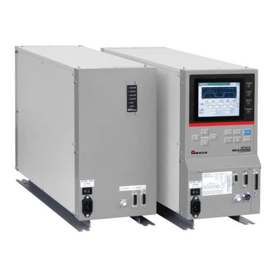
- Page 9 MD Series 2. Features MD-A10000A and MD-B5000A are transistor welding power supplies for precision welding. Small power supply units can be used since all welding is powered by energy accumulated in a capacitor. MD-A10000A: Standard type MD-B5000A: Polarity switching type The switching method adopted for welding current control permits the small model to ■...
- Page 10 MD Series Large current can be supplied by connecting two or more MD-A10000As/ ■ MD-B5000As. MD-A10000A: 12 devices maximum (1 master and 0 to 11 slave(s)) MD-B5000A: 2 devices maximum (1 master and 1 slave) 2. Features...
- Page 11 MD Series 3. Packaging (1) Accessories The model numbers of accessories are subject to change without notice. Depending on the part to be changed, the mounting screw shape may change and a necessary tool may be different. For the latest parts information, contact a nearest sales office.
- Page 12 (100 to 120 V AC) RS-485 connector kit (Connector-mounting L-04742-002 screw, Screw (in mm)) *1: Exclusively for the MD series. Do not use for other devices. MD-A10000A-00-01/-00-03/-00-05/-00-07/-00-09/-00-11/-00-13/-00-15/-00-17/ -00-19/-00-21/-00-23/-00-31/-00-33, MD-B5000A-00-01/-00-31 Item Model No. KP-244 KS-16D VCTF3*1.25mm 3m (For Japan, 200 V AC) CEE3P-W-1.8...
- Page 13 MD Series 4. Name and Functions of Each Section (1) Front (Master) 1Display screen 4READY lamp 3START lamp 5TROUBLE lamp 2POWER lamp 6WELD key/lamp 8MENU key 9RESET key 7Cursor key ENTER key ⑪+ key ⑫- key ⑮RS-485 connector ⑯CONTROL connector ⑰I/O connector...
- Page 14 MD Series 3 START lamp Comes on when the sequence starts after the start signal is input. 4 READY lamp Comes on when the welding current is ready to be supplied to the equipment. The following conditions must be met for this lamp to come on: ・The WELD lamp on the front panel is on.
- Page 15 MD Series ⑯ CONTROL connector Used to connect to the slave. For connection, refer to 5. (2) Connection between Master and Slave. ⑰ I/O connector Pin No. Description INT.24V 24 V DC is output. Connect Pin 1 to Pin 14 to use a contact or NPN transistor (open collector) as input signals (for starting and schedule selection).
- Page 16 MD Series Pin No. Description Fault signal output pins. The circuit is closed when the power supply is turned on. The circuit is opened in the following cases: ・ When the measured value exceeds the range set on the COMPARATOR screen and the PRECHECK screen after the weld sequence is over.
- Page 17 MD Series Pin No. Description PO SEL Input pin for output changeover selection. (This function is provided only for MD-B5000A.) The direction of the welding current flow when the circuit is open is opposite to that when the circuit is closed. (Refer to 5. (5)2MD-B series.)
- Page 18 MD Series Table of schedule Nos. and corresponding schedule-select pins (●: Closed circuit ○: Open circuit) Schedule No. SCH1 SCH2 SCH4 SCH8 SCH16 PARITY ○ ● ○ ○ ○ ○ ○ ○ ● ○ ○ ○ ● ● ● ○...
- Page 19 MD Series (2) Front (Slave) 1OVER CURR lamp OVER CURR 2OVER HEAT lamp OVER HEAT 3OVER CHAR lamp OVER CHAR 4WELD STAR lamp WELD STAR READY 5READY lamp POWER 6POWER lamp SLAVE UNIT 9CURR SENS connector CONTROL connector 7POWER switch...
- Page 20 MD Series 4 WELD STAR lamp Comes on when welding. The START lamp on the master comes on during the weld sequence operation, but the WELD STAR lamp on the slave comes on only during welding. Notes) • In a short welding, it may be hard to see the illumination of the WELD STAR lamp.
- Page 21 MD Series (3) Rear 1Fan motor + 2+ output terminal - 2- output terminal 1 Fan motor Cools the inside of the equipment. 2 +/- output terminals Output terminals for the welding current. Note) Since these output terminals are for the welding current, do not input the external voltage.
- Page 22 MD Series 5. Connection (1) Basic Connection Start signal (Option) Weld force signal (Option) Input from PLC after force end. Input force timing from PLC. (Option) Master Slave Front Welding head OVER CURR OVER HEAT (Option) OVER CHAR WELD STAR...
- Page 23 MD Series (2) Connection between Master and Slave Connect each device with the CONTROL connector and the CURR SIG connector. • Connect each device with the CONTROL connector. There is no rule about the order of connection and you can connect to either connector. Connect them depending on arrangement of devices.
- Page 24 MD Series When connecting 1 master and 2 slaves Master Slave Slave When connecting 1 master and 3 slaves Master Slave Slave Slave When connecting 1 master and 4 slaves Master Slave Slave Slave Slave When connecting 1 master and 5 slaves...
- Page 25 MD Series When connecting 1 master and 6 slaves Master Slave Slave Slave Slave Slave Slave When connecting 1 master and 7 slaves Master Slave Slave Slave Slave Slave Slave Slave 5. Connection...
- Page 26 MD Series When connecting 1 master and 8 slaves Master Slave Slave Slave Slave Slave Slave Slave Slave When connecting 1 master and 9 slaves Master Slave Slave Slave Slave Slave Slave Slave Slave Slave 5. Connection...
- Page 27 MD Series When connecting 1 master and 10 slaves Master Slave Slave Slave Slave Slave Slave Slave Slave Slave Slave When connecting 1 master and 11 slaves Master Slave Slave Slave Slave Slave Slave Slave Slave Slave Slave Slave 5. Connection...
- Page 28 MD Series (3) Connecting Contacts or NPN (Open Collector) Transistors INT.24V INT.24V EXT.COM EXT.COM STOP STOP SCH 1 SCH 1 SCH 2 SCH 2 SCH 4 SCH 4 SCH 8 SCH 8 SCH16 SCH16 PARITY PARITY (PO SEL) (PO SEL)
- Page 29 MD Series (4) Connecting PNP (Source) Transistors INT.24V INT.24V (PNP current output type) (PNP current output type) EXT.COM EXT.COM STOP STOP 24 V DC 24VDC SCH 1 SCH 1 SCH 2 SCH 2 SCH 4 SCH 4 SCH 8 SCH 8...
- Page 30 MD Series (5) Timing Chart 1 MD-A series ・1-step welding (When SCHEDULE MODE on the STATUS screen is set to SINGLE) Schedule select input (SCH1,2,4,8,16) Start input (2ND) Welding current *2*5 End output (END) *2*5 Normal output (GOOD) Fault output...
- Page 31 MD Series ・2-step welding (When SCHEDULE MODE on the STATUS screen is set to DOUBLE) Schedule select input (SCH1,2,4,8,16) Start input (2ND) Welding current *2*5 End output (END) *2*5 Normal output (GOOD) Fault output (NG) Caution output (CAUTION) Remarks SQ: Squeeze time...
- Page 32 MD Series 2 MD-B series ・1-step welding (When SCHEDULE MODE on the STATUS screen is set to SINGLE) Schedule select input (SCH1,2,4,8,16) Start input (2ND) Polarity-switching select input (PO SEL) Welding current (When PO SEL is open) *3*6 End output...
-
Page 33: Table Of Contents
MD Series The selection of fault signal or caution signal can be changed on the ERROR SETTING screen. At this time, the end signal and the normal signal are not output. *4: Monitor calculation time (10 ms) *5: For the output time of end signal and normal signal, refer to 4 External output signal. -
Page 34: 4: Monitor Calculation Time (10 Ms) *5: For The Output Time Of End Signal And Normal Signal, Refer To
MD Series Remarks SQ: Squeeze time RC: Precheck weld time CP: Precheck judgment time (2 ms) U1: Upslope 1 time W1: Weld 1 time D1: Downslope 1 time CL: Cool time U2: Upslope 2 time W2: Weld 2 time D2: Downslope 2 time... -
Page 35: (Sch1,2,4,8,16) *2
MD Series ・2-step welding with polarity switching (When SCHEDULE MODE is set to DOUBLE; POLARITY CHANGE to ON on the STATUS screen) Schdule select input (SCH1,2,4,8,16) Start input (2ND) Polarity-switching select input (PO SEL) Welding current (When PO SEL is open) - Page 36 MD Series *3: When a fault or caution occurs in precheck welding, welding is not performed in W1 and W2 and the fault signal or the caution signal is output. The selection of fault signal or caution signal can be changed on the ERROR SETTING screen.
-
Page 37: Sq Rc Cp W1 Cl W2 Hd
MD Series 3 External input signal ・Selection of schedule number (Common to MD series) Schedule select input (SCH 1) Schedule select input (SCH 2) Schedule select input (SCH 4) Schedule select input (SCH 8) Schedule select input (SCH 16) Parity input... - Page 38 MD Series ・Hold time of start signal (Common to MD series) Start input (2ND) *1:NO HOLD setting *2:WE HOLD setting *3:SQ HOLD setting Welding current End output (END) *1: When START SIG. HOLD on the STATUS screen is set to NO HOLD, turn on the start signal until the end output.
- Page 39 MD Series 4 External output signal (Common to MD series) ・Output time of end signal and normal signal Start input (2ND) Welding current End output (END) Normal output (GOOD) *1: Changes depending on the setting of END SIG. TIME on the STATUS screen.
- Page 40 MD Series The output timing of fault signal and caution signal is as follows. When the monitor value of the precheck welding is outside the setting range, the signal is output after precheck judgment. When the monitor value is outside the setting range, the signal is output with the same timing as that of the end signal.
- Page 41 MD Series 5 Screen display and communication time (Common to MD series) ・When a fault and caution do not occur during welding Start input (2ND) Welding current End output (END) Normal output (GOOD) Communication output time Screen display time Start-waiting time *1: For the timing of the end signal, refer to 1 MD-A series and 2 MD-B series.
- Page 42 MD Series When the start signal is input while the MONITOR screen is displayed, the screen display is canceled to accept the next start. The next start is accepted 5 ms after end output and communication output are complete. When the screen display is canceled to accept the start, the start stability time is [START SIG.
- Page 43 MD Series Screen display time The display time varies by screen. Displays the screen after the start of end output. Menu screen: 46 ms max. SCHEDULE screen: 112 ms max. MONITOR screen: 178 ms max. COMPARATOR screen: 98 ms max.
- Page 44 MD Series 6 Weld force signal (Common to MD series) Weld force output (SOL) Schedule select input/ Start input (SCH1 to 16, 2ND) Welding current The function to control the weld force signal is not provided. Control the weld force by PLC or the like.
- Page 45 +/- key to complete such setting as input of a number or change of ON/OFF. The MD series has various functions, which are set in the respective screens. Press the MENU key on the front panel to display the menu screen.
- Page 46 (2) Setting the Schedule (SCHEDULE Screen) Sets the schedule (welding condition). Up to 31 welding schedules can be set on the MD series. The screen is used to set the length of weld time, weld current and so on. Move the cursor ( ) to SCHEDULE and press the ENTER key to display the SCHEDULE screen as follows.
- Page 47 MD Series (b) TIME Time period of each movement in welding is set in the unit of ms. Refer to 5. (5) Timing Chart for the relation of each period. Time required until appropriate force is applied to the workpiece.
- Page 48 MD Series (3) Displaying the Measured Value (MONITOR Screen) Displays the measured value of current, voltage, power, and resistance at welding. Current is indicated in yellow solid line, Voltage is cyan, Power is green, and Resistance is magenta. Move the cursor ( ) to function key ((d) to (g)) to be selected and press the ENTER key to display the desired screen.
- Page 49 MD Series [When displaying data of two or less] [When displaying data of three or more] 1 Selected measured item CURR : AVE ... Displays the average value of current. CURR : PEAK ... Displays the peak value of current.
- Page 50 MD Series (e) VOLT Selects whether to display the waveform of voltage and the average value/peal value. Refer to (i) for switching of the average value and the peak value. (f) POWER Selects whether to display the waveform of power.
- Page 51 MD Series (b) CURR Set the upper limit (H) and the lower limit (L) of current for WE1 and WE2 respectively. The setting range is 0.00 kA to 9.99 kA, 00.0 kA to 99.9 kA or 000 kA to 999 You can select either AVE (average value) or PEAK (peak value) for upper/lower limit judgment.
- Page 52 MD Series (5) Setting the Precheck Welding (PRECHECK Screen) Screen for setting the weld time and control voltage for precheck welding. The precheck welding is a function to apply a small current under constant-voltage control before regular welding to confirm that the part to weld is set correctly by means of the measured current value.
- Page 53 MD Series (d) CURR(MONITOR) Displays the measured current value of precheck welding. Displays PEAK (peak value) and AVE (average value) respectively. Note) Waveform and measured value hold the latest data of each schedule. When the power is turned off, all values are cleared.
- Page 54 MD Series (6) Changing the Initial Settings (STATUS Screen) Screen for changing the initial settings for the equipment. Detailed settings can be made to suit the customer's operating environment. Thoroughly read this operation manual before changing the initial settings. Setting method ・...
- Page 55 MD Series 1 CHARGE VOLTAGE The charging voltage can be fixed. The settable voltage is 30 V. 2 CURRENT RANGE This equipment permits selection of the current range according to the magnitude of the welding current. Number of Model No.
- Page 56 MD Series 4 CONTROL Selects the welding control method. Combination control of constant-current and constant-voltage controls The constant-voltage control method and the COMB. constant-current-control method function simultaneously, and priority is given to the control method whichever reaches the set value.
- Page 57 MD Series Input the parity so that the sum total of the closed circuits of the schedule-select signal and PARITY signal is an odd number. (Refer to 4. (1)⑰ I/O connector.) 8 END SIG. TIME Selects the output time duration of the end signal.
- Page 58 MD Series ⑭ MONITOR FIRST TIME Sets the interval not calculating the measured value. AVE (average value) measures the interval except upslope and downslope. PEAK (peak value) measures the entire interval of weld time. Upslope and downslope are included in the measurement interval.
- Page 59 MD Series ⑳ COMMUNICATION CONTROL Selects a communication function. No communication One-way communication. DATA The monitor value and error code are output after welding OUTPUT and in the occurrence of error. Two-way communication. Data is output for the communication request from a BI-DIRECTION personal computer, etc.
- Page 60 MD Series ERROR SETTING ○ The signal output when a fault occurred (fault/caution signals) can be set for each item. Fault code Contents E04: NO CURRENT No current E05: NO VOLTAGE No voltage E06: OUT LIMIT OF CURR Fault of current...
- Page 61 MD Series 7. Basic Operation The operation method for the MD-A10000A is given here as an example. The settings to be made are as follows: Schedule No.: Weld sequence: 2-step Precheck function: ON Welding method: COMB. Monitor values: average current and average voltage Change these settings to suit your purpose of use.
- Page 62 MD Series →Enter [OFF] to change the schedule. →Set the output type of trouble signal to NC. →Set the detection start time of no current/no voltage to 0.5 ms. →Set the measurement start time to OFF. →Set the length of weld time to NORMAL.
- Page 63 MD Series 9 Select SCHEDULE and press the ENTER key. → Set the schedule No. to 15. Set the weld time. Set the current and voltage. Move to the welding test. Perform the actual welding and check to see if the welding schedule is set correctly.
- Page 64 MD Series ⑮ Then change the menu screen to the PRECHECK screen. Record the measured value here as well. Record this value. Check the welding state, and repeat operations 9 to ⑮ to obtain an optimal result. ⑯ When welding is satisfactory, set the monitor value.
- Page 65 If E01: MEMORY TROUBLE is displayed again, repair is required. Contact us. SYSTEM ERROR A fault has been detected in the MD series. Once turn off power and turn on again. If E02: SYSTEM ERROR is displayed again, repair is required.
- Page 66 MD Series Name of fault displayed on the screen Explanation of fault and corrective measures NO VOLTAGE The voltage between electrodes is 0.07 V or less. Or the V SENS cable is disconnected. Check the condition and position of the V SENS cable connection.
- Page 67 MD Series Name of fault displayed on the screen Explanation of fault and corrective measures COUNT MEMORY TROUBLE Counts of GOOD COUNT are damaged. The following are conceivable causes of damage of counted data. ・ Strong power noise and electrostatic noise ・...
- Page 68 MD Series 9. External Communication Function (1) Communication Specifications Item Content Transmission mode RS-485, Asynchronous, Half-Duplex Transmission rate 9600, 19200, 38400 bps Start bit: 1, Data bit: 8, Data format Stop bit: 1, Parity bit: Even Output in ASCII code...
- Page 69 MD Series (2) Single-Directional Communication B Mode (COMMUNICATION MODE on STATUS Screen is B MODE) 1-step welding (When SCHEDULE MODE on the STATUS screen is set to SINGLE) Data strings: M: W1, 01, 5.00, 4.50, 4.50, 4.00, 18.0, 0.89 [CR] Ex.) M: W1,01,5.00,4.50,4.50,4.00,18.0,0.89[CR]...
- Page 70 MD Series (When SCHEDULE MODE on the STATUS screen is set to DOUBLE) 2 2-step welding Data strings: M: W1, 01, 5.00, 4.50, 4.50, 4.00, 18.0, 0.89, W2, 5.00, 4.50, 4.50, 4.00, 18.0, 0.89 [CR] Ex.) M: W1,01,5.00,4.50,4.50,4.00,18.0,0.89,W2,5.00,4.50,4.50,4.00,18.0,0.89[CR] Character Item...
- Page 71 MD Series 3 At the occurrence of fault In case of one fault Data strings: E: 01, 06 [CR] B C D Ex.) E: 01,06[CR] In case of five faults Data strings: E: 01, 06, 07, 08, 09, 10 [CR]...
- Page 72 MD Series (3) Single-Directional Communication C Mode (COMMUNICATION MODE on STATUS Screen is C MODE) 1-step welding (When SCHEDULE MODE on the STATUS screen is set to SINGLE) Data strings: M: 01, 01, 001212, kA, W1, 5.00, 4.50, 4.50, 4.00, 18.0, 0.89, 2.00, P, 1.00, 0.50, 1.00 [CR][LF]...
- Page 73 MD Series *1: When CURRENT RANGE on the STATUS screen is *.**kA. *2: When CURRENT RANGE on the STATUS screen is **.*kA. *3: When CURRENT RANGE on the STATUS screen is ***kA. *4: When WELD TIME on the STATUS screen is NORMAL.
- Page 74 MD Series (When SCHEDULE MODE on the STATUS screen is set to DOUBLE) 2 2-step welding Data strings: M: 01, 01, 001212, kA, W1, 5.00, 4.50, 4.50, 4.00, 18.0, 0.89, 2.00, W2, 5.00, 4.50, 4.50, 4.00, 18.0, 0.89, 2.00, P, 1.00, 0.50, 1.00 [CR][LF] Ex.) M: 01,01,001212,kA,W1,5.00,4.50,4.50,4.00,18.0,0.89,2.00,W2,5.00,4.50,4.50,4.00,...
- Page 75 MD Series Character Item Content Range string *.**, 0.00 to 9.99[ms] W2: Weld 2 time (Set time) **.*, 00.0 to 99.9[ms] Welding code (Precheck welding) P (fixed) *.**, 0.00 to 9.99[kA] ,---- **.*, Peak value 00.0 to 99.9[kA] ,---- ****,...
- Page 76 MD Series 3 At the occurrence of fault In case of one fault Data strings: E: 01, 06 [CR][LF] B C D Ex.) E: 01,06[CR][LF] In case of five faults Data strings: E: 01, 06, 07, 08, 09, 10 [CR][LF] B C C C C C Ex.) E: 01,06,07,08,09,10[CR][LF]...
- Page 77 Code Inquiry about Model and ROM version # Device No. I Ex.: Read Model and ROM version of Device No. 01. Host PC -> MD series # ID1 ID2 I [CR] [LF] #01I[CR][LF] MD series -> Host PC ! ID1 ID2 : Model , ROM version [CR] [LF] !01: MD-A10000A,V00-01A[CR][LF] ・When the Device No.
- Page 78 ・Write S13 for Specified code No. (CD1, CD2, CD3). ・See 2 Data code table for the data order. ・Schedule No. for data output from the MD series becomes last-welded Schedule No. # Device No. W Schedule No. Specified Resetting of fault code No.
- Page 79 MD Series 2 Data code table 1) Specified code No. table Specified Content code No. SCHEDULE screen setting (Only when SCHEDULE MODE on the STATUS screen is SINGLE) Changes the conditions of weld sequence. Specify Schedule No. and Specified code No. to perform reading and writing.
-
Page 80: To 9.99[Ka]
Used when SCHEDULE MODE on the STATUS screen is SINGLE. In case of DOUBLE, use Specified code No. S02. Data strings: When reading Device No. 01 and Schedule No. 008 Host PC -> MD series #01R008S01[CR][LF] MD series -> Host PC !01008S01: 0100, 1.00, 5.00, 1.00, 100, kA, 2.00, 1.00 [CR][LF]... - Page 81 Used when SCHEDULE MODE on the STATUS screen is DOUBLE. In case of SINGLE, use Specified code No. S01. Data strings: When reading Device No. 01 and Schedule No. 008 Host PC -> MD series #01R008S02[CR][LF] MD series -> Host PC !01008S02: 0100, 1.00, 5.00, 1.00, 2.00, 1.00, 4.00, 1.00, 100, kA,...
- Page 82 *6: Range depends on CURRENT RANGE on the STATUS screen. 4) Specified code No.: S03 (MONITOR screen) Data strings: When reading Device No. 01 (Set 000 for Schedule No.) Host PC -> MD series #01R000S03[CR][LF] MD series -> Host PC...
-
Page 83: To 9.99[Ka]
Used when SCHEDULE MODE on the STATUS screen is SINGLE. In case of DOUBLE, use Specified code No. S05. Data strings: When reading Device No. 01 and Schedule No. 008 Host PC -> MD series #01R008S04[CR][LF] MD series -> Host PC !01008S04: kA, 2.20, 1.80, 0, 1.20, 0.80, 0, 02.2, 01.8 [CR][LF]... -
Page 84: 0000 To 0999
Used when SCHEDULE MODE on the STATUS screen is DOUBLE. In case of SINGLE, use Specified code No. S04. Data strings: When reading Device No. 01 and Schedule No. 008 Host PC -> MD series #01R008S05[CR][LF] MD series -> Host PC !01008S05: kA, 2.20, 1.80, 3.20, 2.80, 0, 1.20, 0.80, 1.70, 1.30, 0,... - Page 85 MD Series Character Increment/ Item Content Range string Decrement **.*, 00.0 to 99.9[kW] W2: Weld 2 power upper limit *2*3 ****, 0000 to 0999[kW] **.* 00.0 to 99.9[kW] W2: Weld 2 power lower limit *2*3 **** 0000 to 0999[kW] *1: When CURRENT RANGE on the STATUS screen is *.**kA.
-
Page 86: To 1.00[Ms]
MD Series 7) Specified code No.: S06 (PRECHECK screen) Data strings: When reading Device No. 01 and Schedule No. 008 Host PC -> MD series #01R008S06[CR][LF] MD series -> Host PC !01008S06: 1, 1.00, 0.50, kA, 2.20, 1.80, 1.20, 0.80 [CR][LF]... - Page 87 MD Series 8) Specified code No.: S07 (STATUS screen) Data strings: When reading Device No. 01 (Set 000 for Schedule No.) Host PC -> MD series #01R000S07[CR][LF] MD series -> Host PC !01000S07: 00, 3, 1, 0, 3, 2, 0, 1, 1, 0, 0, 3, 00.5, -00.1, 0, 0, 0, 0 [CR][LF]...
- Page 88 MD Series Character Increment/ Item Content Range string Decrement SCHEDULE MODE: Number of steps 0 to 1 0: SINGLE 1: DOUBLE CONTROL: Welding control method 0: CURR 0 to 2 1: VOLT 2: COMB. START SIG.TIME: Start delay time 0: 1ms...
- Page 89 MD Series Character Increment/ Item Content Range string Decrement MONITOR START TIME: Measurement interval setting ***.*, -00.1: OFF -00.1 to 099.9 000.0 to 099.9: measurement start time [ms] WELD TIME: Length of weld time 0 to 1 0: NORMAL 1: LONG...
- Page 90 MD Series 9) Specified code No.: S08 (COMMUNICATION SETTING screen) Data strings: When reading Device No. 01 (Set 000 for Schedule No.) Host PC -> MD series #01R000S08[CR][LF] MD series -> Host PC !01000S08: 0, 0, 01, 0 [CR][LF] A B C D...
- Page 91 MD Series 10) Specified code No.: S09 (ERROR SETTING screen) Data strings: When reading Device No. 01 (Set 000 for Schedule No.) Host PC -> MD series #01R000S09[CR][LF] MD series -> Host PC !01000S09: 0, 0, 0, 0, 0, 0, 0, 0 [CR][LF]...
- Page 92 Used when SCHEDULE MODE on the STATUS screen is SINGLE. In case of DOUBLE, use Specified code No. S12. Data strings: When reading Device No. 01 and Schedule No. 008 Host PC -> MD series #01R008S11[CR][LF] MD series -> Host PC !01008S11: 001212, kA, 2.00, 1.86, 3.20, 2.61, 04.9, 1.40, 1.00, 1.43, 0.75, 1.00...
-
Page 93: To 9.99[Ka]
Used when SCHEDULE MODE on the STATUS screen is DOUBLE. In case of SINGLE, use Specified code No. S11. Data strings: When reading Device No. 01 and Schedule No. 008 Host PC -> MD series #01R008S12[CR][LF] MD series -> Host PC !01008S12: 001212, kA, 2.00, 1.86, 3.20, 2.61, 04.9, 1.40, 1.00, 3.02, 2.73,... -
Page 94: To 9.99[Ka]
MD Series Character Item Content Range string *.**, 0.00 to 9.99[ms] W2: Weld 2 time (Set time) **.*, 00.0 to 99.9[ms] *.**, 0.00 to 9.99[kA] ,---- PRECHECK: Current peak value **.*, 00.0 to 99.0[kA] ,---- ****, 0000 to 0999[kA] ,---- *.**,... - Page 95 Data strings: When reading Device No. 01 (Set 000 for Schedule No.) Host PC -> MD series #01R000S13[CR][LF] MD series -> Host PC (in case of one fault) !01000S13: E06 [CR][LF] MD series -> Host PC (in case of five faults)
-
Page 96: To 99.9
MD Series 14) Range setting and output range of current value and power value Current value Power value Model No. Range Character Range on SCHEDULE Range on Character Range string screen other screens string 1.00kA *.** 0.00 to 1.00[kA] 0.00 to 9.99[kA] **.* 00.0 to 99.9[kW]... -
Page 97: To 9.99
MD Series Current value Power value Model No. Range Character Range on SCHEDULE Range on Character Range string screen other screens string 10.0kA **.* 00.0 to 10.0[kA] 00.0 to 99.9[kA] **** 0000 to 0999[kW] 20.0kA **.* 00.0 to 20.0[kA] 00.0 to 99.9[kA] ****... - Page 98 MD Series 10. Specifications (1) Product Specifications (Items in can be set for each schedule.) Single-phase, 100 V AC-10% to 120 V AC +10% or 200 V AC-10% to Power supply 240 V AC +10% (50/60 Hz) The voltage is cannot be selected. (Fixed on shipment.)
- Page 99 MD Series (Items in can be set for each schedule.) Master: 1 1.00kA/2.00kA/4.00kA/10.0kA Slave: 0 Master: 1 2.00kA/4.00kA/8.00kA/20.0kA Slave: 1 Master: 1 3.00kA/6.00kA/12.0kA/30.0kA Slave: 2 Master: 1 4.00kA/8.00kA/16.0kA/40.0kA Slave: 3 Master: 1 5.00kA/10.0kA/20.0kA/50.0kA Slave: 4 Master: 1 6.00kA/12.0kA/24.0kA/60.0kA Slave: 5...
- Page 100 MD Series MD-A10000A MD-A10000A Master: 1, Slave: 6 Master: 1, Slave: 7 ・0.00–7.00 kA (0.01kA increment) ・0.00–8.00 kA (0.01kA increment) ・00.0–14.0 kA (0.1kA increment) ・00.0–16.0 kA (0.1kA increment) ・00.0–28.0 kA (0.1kA increment) ・00.0–32.0 kA (0.1kA increment) ・00.0–70.0 kA (0.1kA increment) ・00.0–80.0 kA (0.1kA increment)
- Page 101 MD Series 0–999999 Counter Counts only when the current/voltage monitor judgment is good. (MONITOR screen) (Counting continues even if schedules are changed.) Set by START SIG HOLD Self-hold method NO HOLD (There is no self-hold.) (Common to all SQ HOLD (Self-hold from the beginning of SQ)
- Page 102 MD Series (2) Duty Cycle Graph Weld Time : 0 to 20.0 ms (1.30,9.990) 10000A ● Weld cycle : 1 time/sec (1.00,9.990) 9000 ● Load : 1m Ω (1.90,8000) 8000 (1.45,8000) 7000 (3.20,6000) 6000 (2.50,6000) 溶 接 電 5000 流...
- Page 103 MD Series Weld Time : 20.0 to 100.0 ms Welding current 10. Specifications 10-6...
- Page 104 MD Series How to Read the Duty Cycle Graph Ex.) When performing welding with 6000 A in a temperature of 40°C using 1 master and 1 slave (The number of connected devices: 2) Divide the current value by the number of devices to calculate the current per device, and then find the weld time referring to the duty cycle graph based on the obtained current value.
- Page 105 MD Series (5) Schematic MD-A10000A Master Charging part Power block part + + Current OUTPUT sensing part AC INPUT - Control part CONTROL CURR. SIG Operating LCD display part Slave Charging part Power block part + + Current OUTPUT...
- Page 106 MD Series MD-B5000A Master Charging part Power block part + + Current OUTPUT sensing part - AC INPUT Control part CONTROL CURR. SIG Operating LCD display part Slave Charging part Power block part + + Current OUTPUT sensing part -...
- Page 107 MD Series 11. Outline Drawing (1) Master (Dimensions in mm) 8-M8 + - 6-φ9 Back side 23.5 49.5 49.5 (2) Slave (Dimensions in mm) OVER CURR OVER HEAT OVER CHAR WELD STAR READY POWER SLAVE UNIT 8-M8 + - 6-φ9 Back side 23.5...
- Page 108 MD Series 12. Schedule Data Table SCH.# ↗ ↘ COOL ↗ ↘ HOLD CURR VOLT CURR WE1 CURR WE2 CURR AVE/PEAK VOLT WE1 VOLT WE2 VOLT AVE/PEAK POWER WE1 POWER WE2 TIME VOLT HIGH PEAK HIGH ON/OFF 12. Schedule Data Table...
- Page 109 MD Series CHARGE VOLTAGE CURRENT RANGE SCHEDULE MODE CONTROL START SIG. TIME START SIG. HOLD SCHEDULE # END SIG. TIME VOLT RESPONSE KEY LOCK NG SIGNAL TYPE NO CURR MONITOR START MONITOR FIRST TIME WELD TIME POLARITY CHANGE COMMUNICATION CONTROL...
- Page 110 MD Series Index MONITOR Screen ..........6-4 Accessories ............3-1 Options ..............3-2 Outline Drawing............11-1 OVER CHAR lamp ..........4-7 OVER CURR lamp ..........4-7 Basic Connection........... 5-1 OVER HEAT lamp ..........4-7 Board List for Maintenance ........10-7 Polarity switching type ..........2-1 Combination control of constant-current and POWER lamp ..........
Need help?
Do you have a question about the MD Series and is the answer not in the manual?
Questions and answers