Sign In
Upload
Manuals
Brands
Amada Manuals
Welding System
ML-2650B-CDRH
User Manuals: Amada ML-2650B-CDRH YAG Laser Welder
Manuals and User Guides for Amada ML-2650B-CDRH YAG Laser Welder. We have
1
Amada ML-2650B-CDRH YAG Laser Welder manual available for free PDF download: Operation Manual
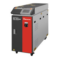
Amada ML-2650B-CDRH Operation Manual (227 pages)
YAG LASER WELDER
Brand:
Amada
| Category:
Welding System
| Size: 10 MB
Table of Contents
Table of Contents
3
How to Use this Document
2
Table of Contents
3
For Use in Safety
7
Safety Precautions
7
Laser Safety Supervisor
10
Precautions for Handling
10
Routine Handling
10
For Transportation
11
For Disposal
15
Sticking Warning/Danger Labels
16
Introduction Part
19
Chapter 1 Overview of the YAG Laser Welder
21
YAG Laser
21
Mechanism of the YAG Laser
22
Functions of the ML-2650B/2651B
23
Product Composition
24
Packaging
24
Checking the Packaged Products
24
Options
27
Chapter 2 Name and Functions of each Section
29
Name and Function of each Section on the Front Side
29
Front Cover Section
29
Inside of the Front Side
30
Name and Function of each Section on the Top Side
32
Top Cover Section
32
Laser Controller (MLE-122A)
33
Laser Oscillator Section
34
Name and Function of each Section on the Lateral Side and Rear Side
36
Installation and Preparation Part
37
Chapter 1 Installation
39
Installation Place
39
Space Required for Installation
39
Environment Suitable for Installation and Precautions
40
Fixing the Laser Welder
42
Cooling Water
44
Required Quantity of Primary Cooling Water
45
Water Quality Standard for Primary Cooling Water
45
Chapter 2 Connections and Preparations of each Section
47
Connecting the Power Supply
47
Connecting the Hose for Primary Cooling Water
48
Preparing the Secondary Cooling Water
49
Connecting the Optical Fiber
50
Removing the Laser Controller
53
Connecting the External Communication Conversion Adapter (Option)
54
Operating Part
55
Chapter 1 Control Method, and Start and Stop
57
Control Method
57
Switching the Control Method
57
Start and Stop
58
How to Start the Laser
58
How to Stop the Laser
58
Chapter 2 Various Settings
59
Setting Welding Schedules
59
Welding Schedule Setting Screen
59
Setting Laser Light Output Schedules (SCHEDULE Screen)
76
Setting the Output Conditions for Seam Welding (SEAM Screen)
81
Setting the Output Status (STATUS Screen)
84
Checking the State of External Input/Output Signals (EXT.I/O MONITOR Screen)
89
Setting the Output Status Check Screen (MONITOR Screen)
90
Protecting Set Values (PASSWORD Screen)
93
Switching the Accuracy of the Measured Laser Energy Value (J) (MEMORY SWITCH Screen)
97
Switching the Pulse Width Setting Range (MEMORY SWITCH Screen)
100
Setting the Laser Light Delivery
103
Laser Light Sharing
103
Operating Branch Shutters on the STATUS Screen
106
Controlling Branch Shutters Independently
107
Changing the Acceptance Time for Laser Start Signal/Schedule Signal (MEMORY SWITCH Screen)
110
Setting the Function of the Output Unit with Fiber Sensor (Option)
113
Chapter 3 Laser Welding by Laser Controller (PANEL CONTROL)
115
Operation Flow
115
Laser Controller Functions
116
Operating Procedure
117
Chapter 4 Laser Welding by External Input/ Output Signals (EXTERNAL CONTROL)
125
Operation Flow
125
Preparations for Operations
126
Connector Functions
127
Pin Arrangement and Functions
127
Example Connections of External Input Signals
135
Example Connection of External Output Signals
137
Programming
138
Chapter 5 Laser Welding by External Communication Control (RS-485 CONTROL)
143
Operation Flow
143
Preparations for Operations
144
Initial Settings
145
Setting Communication Schedules
145
Setting Equipment no
147
Commands
149
Setting Data
151
Reading Data
152
Schedule Settings for both FIX and FLEX
153
Schedule Settings for FIX
153
Settings for the Cooler (Set the Schedule No. [SH1/SH0] to 00.)
153
Schedule Settings for FLEX, TIME 01 to
154
Schedule Settings for FLEX, TIME 11 to
154
Schedule Settings for FLEX, POWER 01 to
155
Schedule Settings for FLEX, POWER 11 to
155
SEAM Setting Value SEAM ON/OFF
155
SEAM Setting Value SHOT 01 to
155
SEAM Setting Value POWER 01 to
156
SEAM Setting Value POWER 11 to
156
SEAM Setting Value SHOT 11 to
156
Laser Power Monitor - Energy, Number of Waveform Data, Etc
157
Laser Power Monitor - Shot Count, Good Count, Average
157
Laser Power Monitor - Waveform Data 000 to
157
Laser Power Monitor - Waveform Data 105 to
157
Schedule No. (SH1 = Tens Digit, SH0 = Units Digit)
159
Setting the Control Method, SCHEDULE No., Branch Shutter, Etc
159
Sh1/Sh0
159
Setting the Mirror of the Timesharing Unit
160
Reading the Control Method, SCHEDULE No., Branch Shutter, Etc
161
Reading the Timesharing Unit Status
162
Starting a Laser Light Output
162
Resetting the Total Number of Outputs
163
Stopping a Laser Light Output
163
Stopping an Error Signal Output
163
Reading Error No. at Occurrence of Trouble
164
Resetting the Appropriate Number of Outputs
164
Chapter 6 Printing Set Values and Measured Values
167
Printing Set Values
167
Printing Measured Values
169
Printing Set Values for Seam Welding
170
Maintenance Part
171
Chapter 1 How to Perform Maintenance
173
Note
173
Maintenance Parts and Standard Intervals of Inspection/Replacement
173
Maintenance of the Cooler Unit Section
176
Cleaning the Solenoid Valve Strainer
176
Draining Water from the Primary Cooling Water
177
Draining Water Form the Secondary Cooling Water Tank
179
Changing the Ion-Exchange Resin and Replacing the Ion-Exchanger
180
Changing the Water Filter and Secondary Cooling Water
183
The Room Temperature at the Installation Place Goes down below 0ºC
184
Maintenance of Laser Oscillator Section
187
Replacing the Flashlamp
187
Making an Incident Beam Adjustment of the Optical Fiber
191
Cleaning the Optical Fiber
191
Cleaning the Optical Parts
192
Maintenance of the Power Supply Section
193
Replacing the Lithium Battery for Backup
193
Cleaning the Air Filter
194
Chapter 2 Inspection and Measure to be Taken at Occurrence of an Error
195
Error Display and How to Take a Measure
195
Operation for Closing Interlock
200
Troubles Not Displaying Fault Code
200
Appendixes
201
Specifications
203
Dimensional Outline Drawings
205
Available Output
206
Timing Chart
208
Explanation of Terminology
214
Output Schedule Data Entry Table
219
Index
225
Advertisement
Advertisement
Related Products
Amada ML-2651B
Amada ML-2651B-CE
Amada ML-2650B
Amada ML-2650B-CE
Amada ML-2651B-CDRH
Amada ML-2351A-CE
Amada ML-2350AF
Amada ML-2350AF-CE
Amada ML-2351AF-CDRH
Amada ML-2451A-CE
Amada Categories
Welding System
Welding Accessories
Power Supply
Transformer
Indoor Furnishing
More Amada Manuals
Login
Sign In
OR
Sign in with Facebook
Sign in with Google
Upload manual
Upload from disk
Upload from URL