Table of Contents
Advertisement
Quick Links
Advertisement
Table of Contents

Subscribe to Our Youtube Channel
Related Manuals for Amada MH-D500D


Summary of Contents for Amada MH-D500D
- Page 1 MOTOR-DRIVEN RESISTANCE WELDING HEAD MH-D500D OPERATION MANUAL AA05OM1208867-02...
-
Page 2: Table Of Contents
MH-D500D Thank you for purchasing our Motor-Driven Resistance Welding Head MH-D500D. ・This operation manual explains its method of operation and precautions for use. ・Before using, read this operation manual carefully; after reading, save it in a proper place where you can easily access. - Page 3 MH-D500D (3) MH-D500D-00-02/03/32/33 Head ····················································· 12-3 (4) MH-D500D-00-42/43 Head ····························································· 12-4 (5) MH-D500D-00-50/51/80/81 Head ····················································· 12-5 (6) MH-D500D-00-90/91 Head ····························································· 12-6 (7) MH-D500D-00-52/53/82/83 Head ····················································· 12-7 (8) MH-D500D-00-92/93 Head ····························································· 12-8 (9) Head Controller ············································································ 12-9...
-
Page 4: Special Precautions
MH-D500D 1. Special Precautions (1) Safety Precautions CAUTION ! Before using, read "Safety Precautions" carefully to understand the correct method Denotes operations and practices that of use. may result in personal injury or damage to the equipment if not correctly followed. - Page 5 MH-D500D WARNING ! Do not put your hands between the electrodes When welding, keep your fingers and hands away from the electrodes. Do not touch any welded part or electrodes during welding and just after welding finished The welded part of a workpiece, electrodes and electrode holder are very hot.
- Page 6 MH-D500D CAUTION ! Do not splash water on the Welding Head Water splashed over the electric parts can cause electric shock and short circuits. Use proper tools (wire strippers, pressure wire connectors, etc) for termination of the connecting cables Do not cut the conductor of wire. A flaw on it can cause fire and electric shock.
-
Page 7: Precautions For Handling
MH-D500D (2) Precautions for Handling Do not install this Welding Head in the following: ■ ・Damp places where humidity is higher than 90%, ・Dusty places, ・Places where chemicals are handled, ・Places near a high noise source, ・Hot or cold places where temperatures are above 40°C or below 0°C, and ・Places where water will be condensed. -
Page 8: Features
MH-D500D 2. Features Since MH-D500D is motor-driven, a piping for an air actuation is not needed, enabling an easy installation. Owing to the motor-driven mechanism, stable electrode force is always obtained although an electrode opening (length) changes. Also, you don’t need to adjust the electrode opening finely when replacing the electrode. -
Page 9: Name And Functions Of Each Section
MH-D500D 3. Name and Functions of Each Section (1) Head ② ⑮ ⑭ ① ⑧ ⑪ ③ ④ ⑫ ⑤ ⑦ ④ ① ⑬ ⑤ ⑥ ⑩ ⑬ ⑨ Weld Force Adjustment Knob ATTENTION Adjusts the electrode force. Should a metal object such as a ... - Page 10 MH-D500D M6 Electrode Holder-Mounting Screw Mounts the electrode Holder to the Holder Upper. Electrode Holders Fixes the electrodes. Holder Mounts the electrode holder. Screws for connecting Voltage Sensing Cable Connects the Voltage Sensing Cables. Use the cables which your welding power supply designates.
-
Page 11: Controller Front Panel
MH-D500D (2) Controller Front Panel Operation Button Operate the Welding Head by turning the button clockwise/counterclockwise or pressing TROUBLE SPEED By turning the button, the lamp illumination HOLD TIME changes as shown: W E L D H E A D... - Page 12 MH-D500D ⑫ [SPEED HOLD TIME] Display Indicate the “electrode speed” and “HOLD Time after the application of weld force is completed”. The larger number indicates the faster electrode speed and the longer HOLD Time. And the lamp lights up simultaneously with other lamps as follows:...
-
Page 13: Controller Rear Panel
MH-D500D (3) Controller Rear Panel [MOTOR CONTROL] Connector It is a connector for controlling a motor to drive the electrode. I/O Connector It is for input/output of signals. Connector for Weld Force detecting Sensor It is for inputting the weld force signal of the welding head. -
Page 14: Interface
MH-D500D 4. Interface (1) Connection Diagram of External Input/Output Signal Motor Head Controller External Input/Output Connector 24VDC ≈ - COM S CH1 S CH2 S CH4 S CH8 S CH16 + COM + COM 1 ST 2 ND Spare: Do not connect... - Page 15 MH-D500D [Example of Connection] ・When contacts are used as input terminal of I/O connector ≈ 24VDC +C O M -COM +COM EXT.COM -COM ・When NPN transistor (sink type) on PLC is used as input terminal of I/O connector ≈ 24VD C...
-
Page 16: I/O Connector
MH-D500D. Before selecting the schedule Input number by the operation button on MH-D500D, open the circuits of all the Pins of No. 2, 3, 4, 5 and 6 in I/O Connector. Input [SCH] signal at least 2 ms before the welding current flows. During in operation, the schedule number cannot be changed. - Page 17 MH-D500D Description Output pins for 24 V DC through 100Ω internal resistor. Input pin for start-up signal. When [1ST] is closed, electrode moves from Start Point to Mid-Point. When [2ND] is closed after [1ST] was closed, electrode moves from Input Mid-Point to Weld Point.
- Page 18 Close at least for 2 ms. Pin 18 does not work while the circuit of Pin 18 is closed. Input pin for prohibition of setting the operation schedule. When Pin 19 is closed, the operation schedule of MH-D500D cannot be set. (The schedule number can be modified.) Spare pin: Do not connect.
- Page 19 Output pin for a trouble signal. ERROR When trouble occurs Output MH-D500D, the Pin becomes OUT CO M opened until it is reset. or 31 Spare pin: Do not connect. Common terminal to [READY], [START POINT], [MID POINT] and [ERROR] Do not connect to the Pin for [EXT.
-
Page 20: Installation And Connection
Connect the grounding wire to the grounding terminal located near the grounding mark. CAUTION ! Be sure to firmly install the MH-D500D on the horizontal place before using. When the distance from welding transformer is shorter, higher work efficiency will be obtained. Determination of Where to Install Determine where to install MH-D500D, the welding power supply and welding transformer. - Page 21 MH-D500D Installation and Replacement of Electrode Loosen M6 bolt fixing Electrode Holder to extract the electrode. Insert the new electrode into the hole of Electrode Holder. Install the new electrode so as to keep the electrode extension always the same.
- Page 22 MH-D500D Connecting Cable of Weld Force Detecting Sensor Connect the cable of Weld Force Detecting Sensor to controller of the motor. Connection of I/O Connector Connect I/O Connector to controller of the motor. 2-level type foot switch is connected to terminals of [1ST], [2ND] and [COM] of I/O Connector (Accessories).
-
Page 23: Operation
Downstop A little bit beyond the position from Weld Point. Point It can be set arbitrarily. Working Mode of Electrode In the model of MH-D500D, it has two working modes. Movement Mode 0 Mode 1 For setting Position Performed by External Input... -
Page 24: Mode Setting
MH-D500D 2 N D Start-up 1 S T O F F SCH No SCH 1 SCH 2 SC H Input S t a r t P o i n t ( S C H 1 ) Electrode S t a r t P o i n t... -
Page 25: Applying Power And Moving To Start Point
MH-D500D Change of ERROR Signal Output Press the operation button while “1” blinks on [SPEED HOLD TIME] Display. Mode No. blinks on [SCH(SCHEDULE)] Display. Rotate the operation button to select “0” or “1”. ・0………means “circuit opened in case of error”... -
Page 26: Auto-Setting Of Electrode Position
MH-D500D (4) Auto-Setting of Electrode Position The electrode position can be set automatically by means of the auto-setting function. Turn the operation button to light up [AUTO] Lamp. Press the operation button for 1 second, and [AUTO] Lamp blinks. Close External Input [1ST], and the electrode moves to Original Point. -
Page 27: Manual Setting Of Electrode Position
MH-D500D (5) Manual Setting of Electrode Position Selecting Schedule No. Turn the operation button to light up [SCH] Lamp. Press the operation button for 1 second. [SCH] Lamp and [SCH] Display blink. Turn the operation button clockwise and counterclockwise to select a numeral (1 to 31) on [SCH] Display. - Page 28 MH-D500D Changing Moving Speed between Start Point and Mid-Point Turn the operation button to light up both [READY] and [MID] Lamp. Press the operation button for 1 second. [READY] and [MID] Lamp blink. The number of blinking [SPEED HOLD TIME] Lamp indicates the current speed setting.
- Page 29 MH-D500D When you want to interrupt the operation, Press [ORG/CANCEL] button, and [MID] Lamp blinks fast. Close External Input [1ST]. The electrode returns to the previous position with beeps. In the case of Mode 1, it works by pressing the operation button in addition to External Input.
- Page 30 MH-D500D [In case that the electrode cannot move beyond Weld Point because of a workpiece] Turn the operation button until the electrode stops, and then press the operation button. Downstop Point is set 5 mm beyond Weld Point and [WELD] Lamp blinks fast.
- Page 31 MH-D500D 2 N D 2 N D Start-up 1 S T O F F END Signal EN D Input Start Point Electrode Mid-Point Movement Weld Point WELD WELD START START Output Additional Pressing Time Setting of Hold Time Turn the operation button to light up [HOLD] Lamp.
-
Page 32: Welding Work
MH-D500D Setting Moving Speed from Weld Point to Mid-Point Turn the operation button to light up both [MID] and [WELD] Lamp. Press the operation button for 1 second. [MID] and [WELD] Lamp blink. The number of the blinking [SPEED HOLD TIME] Lamp indicates the current speed setting. -
Page 33: Measuring Weld Force
MH-D500D After the weld force of the electrode is released, open External Input [both 1ST and 2ND]. Then, the electrode returns to Start Point. In case that External Input [1ST] is closed, the electrode returns to and stops at Mid-Point. -
Page 34: Fault Indications
MH-D500D 7. Fault Indications When a trouble occurs at the apparatus, [TROUBLE] Lamp lights up and a fault code is shown on [SCH] Display. Closing External Input [RESET] or continuing to press the operation button can reset the fault signal. -
Page 35: User's Maintenance
MH-D500D 8. User’s Maintenance ATTENTION ・Use the appropriate tools for the size of screws for maintenance. After the completion of adjustment, tighten the screws firmly so that there may occur no loosening or rattling. ・When a caution is given that denotes “Turn off the power switch of the motor controller”, strictly observe it to avoid an electric shock and incorrect operation. - Page 36 MH-D500D After adjusting, measure the weld force by the use of a pressing force gauge or spring balance. Weld Force Conversion Graph The weld force conversion graph represents theoretical values. To measure the actual weld force, use a pressing force gauge or spring balance.
-
Page 37: Specifications
MH-D500D 9. Specifications (1) Specifications For direct welding MH-D500D-00- Items 00/30 01/31 02/32 03/33 Electrode Force 50–500 N (Approx. 5 to 50 kgf) Stepless adjustment Weld Force Method Spring forced Load Cell Equipped Electrode Dia. 6 mm 8 mm 6 mm... -
Page 38: Accessories
MH-D500D (2) Accessories MH-D500D-00- Name 00/02/30/ 01/03/31/ 50/52/80/ 51/53/81/ 32/40/42 33/41/43 82/90/92 83/91/93 M6 Hexagon rod spanner (Nominal # 5): 1 pc Work Tools M4 Hexagon rod spanner (Nominal # 3): 1 pc 2-Level 1 pc (with Controller) Footswitch 6 dia. x 50 mm 8 dia. -
Page 39: Separately Sold Items
CEE3P-W-1.8* Round plug, for 200-240 V AC 3-pin/2-pin conversion adapter for KPR-24(SB)-B power cable, for 100-120 V AC * Exclusively for the MH-D500D. Do not use for other devices. Start Cable at Set Weld Force Model Specification A-05986-001 For separately-installed type of controller... -
Page 40: Timing Chart
MH-D500D (4) Timing Chart Power ON and Error occurring Switch of O N Apparatus O F F O N Power Supply to Motor O F F 1ST or ORG Start-up O F F Original Original Point Point Start Start... -
Page 41: Data Communication
MH-D500D 10. Data Communication (1) Communication Specifications RS-232C: RS-232C, Asynchronous, Teletype procedure Method RS-485: RS-485, Asynchronous, Half-Duplex Transmission 9600 bps rate Start bit: --------- 1 Data bit: --------- 8 Data type Stop bit: --------- 1 Parity bit: -------- 1 (Even parity) - Page 42 MH-D500D RS-485 Signals of RS-485 use (RS+) and (RS-). Short-circuit between Pins 7 and 10. MH-D500D MH-D500D External connector Pin No. TRO U BLE SPEE D HOLD TIM E Host Computer WELD HEAD REA D Y CONTROL UNIT WEL D...
-
Page 43: Bidirectional Communication
When the electrode is at Start Point, the schedule data can be read or written. When the readout/overwrite command is sent from the host computer, MH-D500D sends back the data. When sending the command, do not send the next command until the data are sent back or the timeout time elapses. - Page 44 MH-D500D ・MH-D500D→Host Controller Character Item Order Description Range train Communication start 01-01 Fixed (to host) 02-03 Communication ID Fixed 04-06 Schedule No. 001 to 031 07-07 Data start Fixed 00000 to 05000 08-13 nnnnn, Start Point (nnn.nn, unit in mm)
- Page 45 MH-D500D Overwrite Command ・Host Controller→MH-D500D Character Item Order Description Range train Communication start 01-01 Fixed (from host) 02-03 Communication ID Fixed 04-04 Overwrite request Fixed 05-07 Schedule No. 001 to 031 08-08 Data start Fixed 00000 to 05000 09-14...
- Page 46 MH-D500D ・MH-D500D→Host Controller Character Item Order Description Range train Communication start 01-01 Fixed (to host) 02-03 Communication ID Fixed 04-06 Schedule No. 001 to 031 07-07 Data start Fixed 00000 to 05000 08-13 nnnnn, Start Point (nnn.nn, unit in mm)
-
Page 47: Welding Head With Load Cell
MH-D500D 11. Welding Head with Load Cell (1) Connection of Load Cell Sensor to Indicator Connect cables of a load cell sensor to the signal input/output terminal block at the back panel of Indicator DS-6200 (See Load Cell Connection in Operation Manual of Indicator.) - Page 48 MH-D500D The way to set the values is described below (See Comparison Functions in Operation Manual of Indicator). 11. Welding Head with Load Cell 11-2...
-
Page 49: How To Hold Hi-Lo Limit Judging And Indicated Value At Indicator
MH-D500D (3) How to Hold at Indicator HI-LO Limit Judging and Indicated Value After Upper and Lower Limit has been judged at Indicator, the displayed value can be held by the use of external devices such as PLC (Sequencer), etc. (See Comparison Functions in Operation Manual of Indicator for the way to set Upper and Lower Limit). -
Page 50: Calibration Of Load Cell
MH-D500D (4) Calibration of Load Cell The way to calibrate the built-in load cell is described below. A pressing force gauge is necessary for measuring weld force across electrodes. Calibrate Indicator with a load cell sensor by the Equivalent Input Calibration. -
Page 51: Outline Drawings
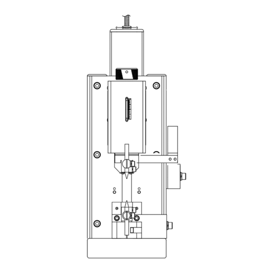
MH-D500D 12. Outline Drawings Note that the configuration of the Head differs depending on the model number. (1) MH-D500D-00-00/01/30/31 Head (Dimensions in mm) 4-φ8.5 Spot Facing: φ14, 8.5 depth (290) (Head Mounting Hole) 12. Outline Drawings 12-1... -
Page 52: Mh-D500D-00-40/41 Head
MH-D500D (2) MH-D500D-00-40/41 Head (Dimensions in mm) 4-φ8.5 Spot Facing: φ14, 8.5 depth (290) (Head Mounting Hole) 12. Outline Drawings 12-2... -
Page 53: Mh-D500D-00-02/03/32/33 Head
MH-D500D (3) MH-D500D-00-02/03/32/33 Head (Dimensions in mm) Load Cell Indicator 4-φ8.5 Spot Facing: φ14, 8.5 Depth (330) (Head Mounting Hole) Load Cell Indicator (119) 12. Outline Drawings 12-3... -
Page 54: Mh-D500D-00-42/43 Head
MH-D500D (4) MH-D500D-00-42/43 Head (Dimensions in mm) Load Cell Indicator 4-φ8.5 Spot Facing: φ14, 8.5 depth (330) (Head Mounting Hole) Load Cell Indicator (119) 12. Outline Drawings 12-4... -
Page 55: Mh-D500D-00-50/51/80/81 Head
MH-D500D (5) MH-D500D-00-50/51/80/81 Head (Dimensions in mm) Mounting Surface (Customer side) Mounting Screw: M8 6-φ8.5 Spot Facing: φ14, 8.5 depth (Head Mounting Hole) 12. Outline Drawings 12-5... -
Page 56: Mh-D500D-00-90/91 Head
MH-D500D (6) MH-D500D-00-90/91 Head (Dimensions in mm) Mounting Surface (Customer side) Mounting Screw: M8 6-φ8.5 Spot Facing: φ14, 8.5 depth (Head Mounting Hole) 12. Outline Drawings 12-6... -
Page 57: Mh-D500D-00-52/53/82/83 Head
MH-D500D (7) MH-D500D-00-52/53/82/83 Head (Dimensions in mm) DS-6200 33 30 4-φ7 Load Cell Indicator Mounting Surface (Customer side) Mounting Screw: M8 6-φ8.5 Spot Facing: φ14, 8.5 depth (Head Mounting Hole) 12. Outline Drawings 12-7... -
Page 58: Mh-D500D-00-92/93 Head
MH-D500D (8) MH-D500D-00-92/93 Head (Dimensions in mm) 33 30 4-φ7 Mounting Surface (Customer side) Load Cell Indicator Mounting Screw: M8 6-φ8.5 Spot Facing: φ14, 8.5 depth (Head Mounting Hole) 12. Outline Drawings 12-8... -
Page 59: Head Controller
MH-D500D (9) Head Controller (Dimensions in mm) TROUBLE SPEED HOLD TIME WELD HEAD READY CONTROL UNIT WELD HOLD AUTO ORG/CANCEL CHECK FORCE 245.5 Connector Connector for Weld Force Motor Control detecting Sensor Cable Power Input 100 to 240 VAC 12. Outline Drawings...
Need help?
Do you have a question about the MH-D500D and is the answer not in the manual?
Questions and answers