
Related Manuals for Amazone FT 1502


Summary of Contents for Amazone FT 1502
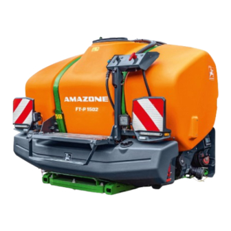
- Page 1 Operating Manual AMAZONE FT 1502 Front tank for the UF02 mounted field sprayer Please read this operating manual before commissioning. MG7554 BAG0205.4 09.22 Keep it in a safe place Printed in Germany for future use. en_US...
- Page 2 Reading the instruction Manual and following it should seem to be in- convenient and superfluous as it is not enough to hear from others and to realize that a machine is good, to buy it and to believe that now everything should work by itself.
- Page 3 + 49 5405-501-0 E-mail: + amazone@amazone.de Spare part orders Spare parts lists are freely accessible in the spare parts portal at www.amazone.de. Please send orders to your AMAZONE dealer. Formalities of the operating manual Document number: MG7554 Compilation date: 09.22 ...
-
Page 4: Table Of Contents
Table of Contents User Information ..................6 General safety instructions ................ 6 Obligations and liability......................6 Representation of safety symbols ................... 8 Organisational measures ......................9 Safety and protection equipment .................... 9 Informal safety measures ......................9 User training .......................... 10 Safety measures in normal operation ................... - Page 5 Table of Contents Fastening the front tank supply lines on the tractor ............... 44 Coupling and uncoupling the machine ............ 45 Coupling the machine ......................45 Uncoupling the machine ......................47 Transportation ................... 48 FT1502 BAG0205.4 09.22...
-
Page 6: User Information
User Information User Information The User Information section provides information on use of the oper- ating manual. General safety instructions This section contains important information on safe operation of the machine. Obligations and liability Comply with the instructions in the operating manual Knowledge of the basic safety information and safety regulations is a basic requirement for safe handling and fault-free machine operation. - Page 7 General safety instructions then they should report this fault to their superior (operator). Risks in handling the machine The machine has been constructed to the state-of-the art and the recognised rules of safety. However, operating the machine may cause risks and restrictions to the health and safety of the user or third parties, •...
-
Page 8: Representation Of Safety Symbols
General safety instructions Representation of safety symbols Safety instructions are indicated by the triangular safety symbol and the highlighted signal word. The signal word (DANGER, WARNING, CAUTION) describes the gravity of the risk and has the following sig- nificance: DANGER Indicates an immediate high risk which will result in death or serious physical injury (loss of body parts or long term damage) if not avoided. -
Page 9: Organisational Measures
General safety instructions Organisational measures The operator must provide the necessary personal protective equip- ment as per the information provided by the manufacturer of the crop protection agent to be used, such as: Chemical-resistant gloves, • Chemical-resistant overalls, • Water-resistant footwear, •... -
Page 10: User Training
General safety instructions User training Only those people who have been trained and instructed may work with/on the machine. The operator must clearly specify the responsi- bilities of the people charged with operation and maintenance work. People being trained may only work with/on the machine under the supervision of an experienced person. -
Page 11: Danger From Residual Energy
General safety instructions Danger from residual energy Note that there may be residual mechanical, hydraulic, pneumatic and electrical/electronic energy on the machine. Use appropriate measures to inform the operating personnel. You can find detailed information in the relevant sections of this operating manual. -
Page 12: Spare And Wear Parts And Aids
Immediately replace any machine parts which are not in a perfect state. Only use genuine AMAZONE spare and wear parts or those approved by AMAZONEN-WERKE so that the type approval remains valid ac- cording to the national and international regulations. The use of spare... -
Page 13: Warning Symbols And Other Signs On The Machine
General safety instructions 2.13 Warning symbols and other signs on the machine Always keep all the warning symbols on the machine clean and in a legible state. Replace illegible warning symbols. You can obtain the warning symbols from your dealer using the order number (e.g. MD 075). -
Page 14: Positions Of Warning Symbols And Other Labels
General safety instructions 2.13.1 Positions of warning symbols and other labels Warning symbols The following pictures show the positions of the warning symbols on the machine. MD 095 Read and follow the operating manual and safety information before starting up the machine! FT1502 BAG0205.4 09.22... - Page 15 General safety instructions MD 097 Risk of crushing the entire body due to standing in the stroke area of the three-point suspension when the three-point hydraulics are actuated. This danger can cause extremely serious and potentially fatal injuries. Personnel are prohibited from entering the •...
-
Page 16: Dangers If The Safety Information Is Not Observed
General safety instructions MD 162 Maximum support load 800kg per transport roller. MD 173 Risk of breathing in hazardous materials via poisonous vapours from the spray liquid tank. This danger can cause extremely serious and potentially fatal injuries. Never climb into the spray liquid tank. MD 245 This danger can cause extremely serious and potentially fatal injuries. -
Page 17: Safety Information For Users
General safety instructions 2.16 Safety information for users WARNING Risk of crushing, cutting, catching, being drawn in or impacts from inadequate roadworthiness and operational safety. Before starting up the machine and the tractor, always check their roadworthiness and operational safety. 2.16.1 General safety and accident prevention information Beside these instructions, comply with the generally applicable... - Page 18 General safety instructions When coupling and uncoupling machines, move the support • equipment (if available) to the appropriate position (stability). • When actuating the support equipment, there is a risk of injury from crushing and cutting points. Be particularly careful when coupling the machine to the tractor •...
- Page 19 General safety instructions Machine transportation Comply with the national road traffic regulations when using • public highways. • Before moving off, check: ο the correct connection of the supply lines ο the lighting system for damage, function and cleanliness the brake and hydraulic system for visible damage ο...
-
Page 20: Field Sprayer Operation
General safety instructions 2.16.2 Field sprayer operation Comply with the recommendations provided by the manufacturer • of the crop protection product with regard to ο personal protective equipment ο warnings concerning the handling of crop protection prod- ucts regulations on dosing, applications and cleaning ο... - Page 21 Do not fill field sprayers with water from bodies of water which • are open to the public, for the protection of people, animals and the environment. • Fill the field sprayer only using original AMAZONE filling devices! FT1502 BAG0205.4 09.22...
-
Page 22: Cleaning, Maintenance And Repairs
Spare parts must meet at least the specified technical require- • ments of AMAZONEN-WERKE. This is ensured through the use of genuine AMAZONE spare parts. When repairing field sprayers which have been used for liquid • fertiliser application with ammonium nitrate / urea solution, ob-... -
Page 23: Loading And Unloading
Loading and unloading Loading and unloading Loading using a lifting crane The machine has: Two attachment points in front (1) • One attachment point in back (1), • CAUTION When loading the machine using a lifting crane, use the marked at- tachment points (1) for lifting belts. -
Page 24: Product Description
Product description Product description Overview (1) Hopper (2) Fill level indicator with scale (3) Screw lid / folding cover (4) FlowControl internal cleaning hose (5) Connection hose to the field sprayer with 2-inch camlock coupling (6) Hose bracket (7) Three-point mounting frame (8) Residual emptying (9) Transport device (1) Switch tap... -
Page 25: Flowcontrol On Uf02 Overview
Product description FlowControl on UF02 overview (1) Fill FT injectors (2) Empty FT injectors (3) Volumetric remote control (4) Fill FT valve (5) Empty FT valve (6) Pressure relief valve FT1502 BAG0205.4 09.22... -
Page 26: Technical Data
Product description Technical data FT1502 Type Tank nominal volume 396 gal 1500 l Tank actual volume 439 gal 1660 l Filling height with rolling device 64 in 1631 mm Total height with rolling device 70 in 1767 mm Total width 88 in 2236 mm Total length... -
Page 27: Intended Use
Crop protection agents (only with Flow Control) is designed exclusively for agricultural use for treating field crops • in combination with the AMAZONE UF02 field sprayer. • is attached to the category 2 front hydraulic system of the tractor and operated by one person. -
Page 28: Danger Areas And Danger Points
Product description Danger areas and danger points The danger area is the area around the machine in which people can be caught by: work movements made by the machine • unintentional rolling of the tractor and the machine • Within the machine danger area, there are danger points with perma- nent or unexpected risks. -
Page 29: Rating Plate
Product description Rating plate (1) Implement number (2) Vehicle identification number (3) Product (4) Permissible technical implement weight (5) Tare weight kg (6) Model year (7) Year of manufacture Three-point attachment frame The frame of the FT front tank is designed to meet the requirements and dimensions of the three-point attachment of category II. -
Page 30: Transport Device (Removable)
Product description Transport device (removable) The removable transportation device enables easy coupling to the tractor's three-point hydrau- lic system and easy manoeuvring in the yard and indoors. To prevent the machine from rolling, the castors are equipped with a locking system. WARNING When installing/removing the trans- portation device, secure the raised... -
Page 31: Transportation Equipment
Product description Transportation equipment (1) 2 front limiting lights (2) Reflector (3) 2 warning signs (4) Side reflector FT1502 BAG0205.4 09.22... -
Page 32: Non-Certified Camera System
Product description 4.10 Non-certified camera system The non-certified camera system is used for monitoring the surroundings and as a manoeu- vring aid. It is used for cross-traffic monitoring with front- mounted implements. The non-certified camera system does not replace the banksman. The implement can be equipped with one or several cameras. -
Page 33: Ft1502 Without Flow Control
FT1502 without Flow Control FT1502 without Flow Control Filling the front tank via the UF field sprayer The front tand is filled via the quick emptying connection of the UF02. Fig. 1 Before filling the front tank, open its screw lid to ventilate it. Close the lid again after filling it. - Page 34 FT1502 without Flow Control 4. Run the pump. 5. Pressure valve chest DA in position 6. Switch tap IJ in position 0. Comfort Package: TwinTerminal: ο Select suction filling ο Enter a target fill level for the UF02 (greater than the actual fill level of the UF02).
-
Page 35: Filling The Uf Spray Liquid Tank Via The Front Tank
FT1502 without Flow Control Filling the UF spray liquid tank via the front tank 1. Couple the connection hose from the front tank (1) to the filling connection (2). 2. Switch tap on front tank (3) in position 3. Run the pump. 4. - Page 36 FT1502 without Flow Control No Comfort Package: Suction valve chest SA in position ο → The UF02 is filled. Pay attention to the fill level indicator on the field sprayer. When the tank is full: 7. Suction valve chest SA in position 8.
-
Page 37: Ft1502 With Flow Control (Optional)
FT1502 with Flow Control (optional) FT1502 with Flow Control (optional) With Flow Control, the front tank is used in combination with the in- cab terminal as an additional container for spray liquid. Flow Control operates in two modes: Automatic mode •... -
Page 38: Connect Field Sprayer With Flow Control And Front Tank
FT1502 with Flow Control (optional) Connect field sprayer with Flow Control and front tank To connect the field sprayer to the front tank, connect the following: (1) Front tank inflow hose line (2) Front tank outflow hose line (3) Connector cable of the filling level indicator (4) Hose line for internal cleaning To use the field sprayer without the front tank and Flow Control (5) Couple the front tank inflow with the outflow. -
Page 39: Flowcontrol And Isobus
FT1502 with Flow Control (optional) FlowControl and ISOBUS Modus Automatic / Manual Switching the pump to the front on / off Switch the pump to the rear on / off Display in the Work menu: (1) Automatic mode switched off. (2) Manual mode switched on (3) Pumps switched on from FT to UF (4) Pumps switched on from UF to FT... -
Page 40: Filling
FT1502 with Flow Control (optional) Filling See operating manual for field sprayer ISOBUS software. The front tank is filled via the field sprayer UF. Before filling the front tank and field sprayer together, adjust the • indicator limit for the fill level. •... -
Page 41: Pump Maintenance
FT1502 with Flow Control (optional) Pump maintenance For maintenance of the pump, also refer to the UF operating manual. 6.7.1 Adjust the air pressure in the pressure reservoir The pressure reservoir (1) attenuates the pres- sure peaks. Required air pressure in the pressure reservoir: 3.0 bar Check air pressure annually Check and correct the air pressure at the air... -
Page 42: Replacing The Pressure Reservoir Diaphragm
FT1502 with Flow Control (optional) 6.7.2 Replacing the pressure reservoir diaphragm CAUTION Before removing the pressure reservoir cover (1), bleed the air pressure from the pressure reservoir (2) via the air valve (3). 1. Remove the pressure reservoir cover (1) after unscrewing the four nuts. -
Page 43: Commissioning
Commissioning Commissioning This section contains information • on commissioning your machine. • on checking if it is possible to connect the machine to your trac- tor. Before operating the machine for the first time the operator must • have read and understood the operating manual. •... -
Page 44: Fastening The Front Tank Supply Lines On The Tractor
Commissioning Fastening the front tank supply lines on the tractor To fasten the supply lines (1) you will need holders not included in the delivery. Supply lines for the front tank with Flow Control • Front tank inflow hose line •... -
Page 45: Coupling And Uncoupling The Machine
Coupling and uncoupling the machine Coupling and uncoupling the machine When coupling and uncoupling the machine, comply with the section "Safety information for the user", page 17. WARNING Risk of crushing from unintentional starting and rolling of the tractor and machine when coupling or uncoupling the machine. When coupling or uncoupling the machine, secure the tractor and machine against unintentional start-up and rolling before entering the danger area between the tractor and machine;... - Page 46 Coupling and uncoupling the machine WARNING Risk of crushing, being caught or pulled in, or impact when the machine is unexpectedly released from the tractor. • Use the intended equipment to connect the tractor and the ma- chine in the proper way. When coupling the machine to the tractor's three-point hydraulic •...
-
Page 47: Uncoupling The Machine
Coupling and uncoupling the machine Uncoupling the machine WARNING Risk of crushing and/or impact due to insufficient stability and the machine tipping over on • soft or uneven ground. due to the machine unintentionally rolling when parked on a • transportation device. -
Page 48: Transportation
Transportation Transportation WARNING Risk of crushing, cutting, being caught and/or drawn in, or im- pact through unintentional releasing of the coupled machine. Carry out a visual check that the upper and lower link pins are firmly fixed with the linchpin against unintentional release. WARNING Risk of crushing, cutting, being caught and/or drawn in, or im- pact from tipping and insufficient stability. - Page 49 Transportation FT1502 BAG0205.4 09.22...
Need help?
Do you have a question about the FT 1502 and is the answer not in the manual?
Questions and answers