Table of Contents
Advertisement
Quick Links
Advertisement
Table of Contents

Subscribe to Our Youtube Channel
Related Manuals for Viking VFBQ6203T1LSS


Summary of Contents for Viking VFBQ6203T1LSS
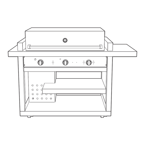
- Page 1 Service Manual Frontgate Gas Grill VFBQ6203T1LSS...
-
Page 2: Table Of Contents
Ignition Mo dule .............. 15 Grill Igniter ..............16 Battery R eplacement ............17 Parts Location–Burners ..........18 Grill Burner ..............19 Component Testing ............20 Troubleshooting Guide ........... 20 WIRING AND SCHEMATICS VFBQ6203T1LSS Wiring Diagram ........21 © 2011 Viking Preferred Service... -
Page 3: Important Information
“DANGER”, “WARNING” or “CAUTION”. These words mean: CAUTION DANGER VIKING will not be responsible for any injury Immediate hazards which WILL result in severe or property damage from improper service personal injury or death. procedures. If performing service on your... -
Page 4: Warranty Information
Viking Range Corporation service agency or representative. This warranty does not apply to commercial usage. Warrantor is not responsible for consequential or incidental damage whether arising out of breach of warranty, breach of contract, or otherwise. -
Page 5: Warranty Service
The return of the Owner Registration Card is not a condition of warranty coverage. You should, however, return the Owner Registration Card so that Viking Range Corporation can contact you should any question of safety arise which could affect you. - Page 6 . 1 c . 4 0 ( 1 1 ” 7 . 9 ” . 5 5 . 6 c ( 7 7 2 . 5 ” ( 6 . 4 © 2011 Viking Preferred Service © 2011 Viking Preferred Service...
-
Page 7: Warnings
If obstructions can be seen, installed in or on recreational vehicles and/or use a metal wire coat hanger that has been straightened out. Shake out any debris through boats. the air shutter. © 2011 Viking Preferred Service © 2011 Viking Preferred Service... - Page 8 flammable vapors and liquids in the vicinity of this or any other appliance. 2. Any LP cylinder not connected for use shall not be stored in the vicinity of this or any other appliance. © 2011 Viking Preferred Service © 2011 Viking Preferred Service...
-
Page 9: Built-In Information
Ensure there is adequate area for it to dissipate. Conversions should only be performed by an authorized service technician. IMPORTANT: Gas fittings, regulator, and installer supplied shut-off valve must be easily accessible. © 2011 Viking Preferred Service © 2011 Viking Preferred Service... -
Page 10: Model - Serial Number Matrix
M A D E I N T H E U S A PRESSION TUBULARE: NAT 4” WCP (1246 PA) PROPANE 10” WCP (2492 Pa) MODEL VFBQ6203T1LSS NUMBER SERIAL 030111C0007498 NUMBER 120 VAC / 60 HZ MAXIMUM AMPS 2.2 © 2011 Viking Preferred Service © 2011 Viking Preferred Service... -
Page 11: Operation
“OFF,” wait 5 minutes, and try again. If the burner will not light If the burner will not light after several attempts, see the Troubleshooting section. © 2011 Viking Preferred Service © 2011 Viking Preferred Service... -
Page 12: Before You Begin
WARM 150˚F (65˚C) COLD SMOKE 150˚F — 200˚F (65˚C — 93˚C) SMOKE 200˚F — 300˚F (93˚C — 149˚C) GRILL 300˚F — 750˚F (149˚C — 399˚C) E-Series canopy thermometer °F © 2011 Viking Preferred Service © 2011 Viking Preferred Service... -
Page 13: Service Diagnostics And Procedures
Service Diagnostics and Procedures Parts Location–Control Panel Access panel removed Grill Grill Grill Ignition Module Igniter Igniter Igniter Grill Grill Grill Valve Valve Valve © 2011 Viking Preferred Service... -
Page 14: Control Panel Access
Verify the switch reads open in the extended 4. Lower the control panel onto drip tray. position and 0 in the pressed position. Note: Make sure to replace with a momentary switch Control Panel Drip Tray 5. Reverse procedure to reassemble. © 2011 Viking Preferred Service... -
Page 15: Ignition Module
Verify the 9 VDC battery is proper. If voltage is proper and no spark is present at the igniter, check the switch, igniter, and wiring. If all check good, replace the module. Ignition module Screws © 2011 Viking Preferred Service... -
Page 16: Grill Igniter
If the igniter shows 0 , ensure power to the igniter from the module. If power is supplied to the igniter and no spark, replace the igniter. Test Points Igniter Wire © 2011 Viking Preferred Service... -
Page 17: Battery Replacement
2. Locate round black cap, which is inside the burner box under the battery symbol on the control panel. Battery Symbol Battery Cap Note: Round black cap that holds battery is located underneath control panel and behind drip tray. © 2011 Viking Preferred Service... -
Page 18: Parts Location-Burners
Service Diagnostics and Procedures Parts Location–Burners Grill Grill Grill Burner Burner Burner © 2011 Viking Preferred Service... -
Page 19: Grill Burner
If supply is proper and still no flow, verify gas valve and orifice. If orifice or air shutter is not plugged and still not flowing, replace the gas valve. © 2011 Viking Preferred Service... -
Page 20: Component Testing
Verify spark at thermocouple. Burner light, but will not Thermocouple Verify thermocouple is not kinked. hold flame once button is Safety valve button Hold button until burner remains lit. released Infrared screen Verify no black spots on screen. © 2011 Viking Preferred Service... -
Page 21: Wiring And Schematics
Wiring and Schematics VFBQ6203T1LSS Wiring Diagram © 2011 Viking Preferred Service...
Need help?
Do you have a question about the VFBQ6203T1LSS and is the answer not in the manual?
Questions and answers