Table of Contents
Advertisement
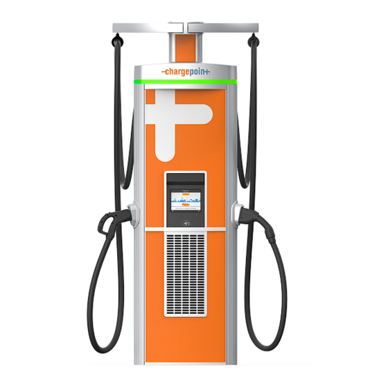
Express 280
Express 280 Specifications
Station Electrical Input
Input Rating
Wiring
Short Circuit Current Rating
Station Electrical Output
Max Output Power
Output Voltage, Charging
Max Output Current
Max Power Modules per Station
Paired Station Electrical Output
Paired Max Output Power
Output Voltage, Charging
Paired Max Output Current
Power Modules per Pair
Power Module Output
Max Output Power
Max Output Current
Power Conversion Efficiency
Power Factor
ChargePoint, Inc. reserves the right to alter product offerings and specifications at any time without notice, and is
not responsible for typographical or graphical errors that may appear in this document.
ChargePoint, Inc. | Copyright © 2022
North America: 3-phase, 480WYE VAC (91.5 kVA), 100 A, 60 Hz
Europe: 3-phase, 400WYE VAC (91.5 kVA), 128 A, 50 Hz
L1, L2, L3, Earth
65 kA
80 kW
100 to 1000 VDC
CHAdeMO (North America): 140 A
CHAdeMO (Europe): 125 A
CCS1: 200 A
CCS2: 200 A
2
160 kW
100 to 1000 VDC
CHAdeMO (North America): 140 A
CHAdeMO (Europe): 125 A
CCS1: 250 A
CCS2: 250 A
4
40 kW
100 A
Up to 96%
0.99 at full load
ChargePoint Express 280 Datasheet
1
Advertisement
Table of Contents

Subscribe to Our Youtube Channel
Related Manuals for ChargePoint Express 280


Summary of Contents for ChargePoint Express 280
- Page 1 Power Factor 0.99 at full load ChargePoint, Inc. reserves the right to alter product offerings and specifications at any time without notice, and is not responsible for typographical or graphical errors that may appear in this document. ChargePoint, Inc. | Copyright © 2022...
- Page 2 Service and Maintenance Remote system monitoring, diagnostic, and proactive maintenance ChargePoint, Inc. reserves the right to alter product offerings and specifications at any time without notice, and is not responsible for typographical or graphical errors that may appear in this document.
- Page 3 It may not be modified, reproduced, or distributed without the prior, express written consent of ChargePoint, Inc. CHARGEPOINT is a US, UK, and EU registered trademark and service mark of ChargePoint, Inc. and cannot be used without the prior written consent of ChargePoint.
- Page 4 Express 280 DC Fast Charging Station Site Design Guide for Standalone and Paired Stations...
-
Page 5: Important Safety Instructions
Read and follow all warnings and instructions before servicing, installing, or operating the ChargePoint® charging station. Install and operate only as instructed. Failure to do so may lead to death, injury, or property damage, and will void the Limited Warranty. - Page 6 Copyright and Trademarks ©2013-2023 ChargePoint, Inc. All rights reserved. This material is protected by the copyright laws of the United States and other countries. It may not be modified, reproduced, or distributed without the prior, express written consent of ChargePoint, Inc.
-
Page 8: Table Of Contents
Contents Important Safety Instructions 1 Site Design Guidelines Accessing ChargePoint Documentation Pairing Two Express 280s Initial Site Guidelines Plan for Future Charging Capacity Charging Station Placement 2 Civil and Mechanical Design Component Dimensions and Weight Mounting Specifications for Pads Drainage... -
Page 9: Site Design Guidelines
Site Design Guidelines This document describes how to design an installation site for the ChargePoint® Express 280 DC fast charging station and install the Concrete Mounting Template, before station installation. An Express 280 station can be installed to operate by itself (called “Standalone”) or to share power with one other Express 280 station for higher throughput (called “Paired”). -
Page 10: Pairing Two Express 280S
Pairing Two Express 280s The Express 280 can be installed either as a standalone system, or paired with another Express 280 using a DC connection to more flexibly share load. The two Power Modules in the base of each charging station can be shared in any combination according to charging need. -
Page 11: Plan For Future Charging Capacity
Plan for Future Charging Capacity ChargePoint recommends planning to install charging stations for 5-10% of parking spaces, or 10-15% for high electric vehicle (EV) adoption areas like California. Designing electrical infrastructure to support current and future needs for EV charging helps avoid costly modifications later as demand for EV charging grows. - Page 12 The Express 280 can have different charging cable types (CCS1 and CHAdeMO) to offer flexibility, or it can have two of the same cable type. The cables cannot both charge at the same time.
- Page 13 Two cable lengths are available: Standard length cables are 5.4 m (17 ft 8 1/2 in) long and are used with standard Cable Management Kits (CMK) Medium length cables are 7.6 m (24 ft 11 1/4 in) long and are used with longer cable management systems IMPORTANT: Place each charging station to maximize cable reach for the varied charge port...
- Page 14 Charging Station Placement Cable reach radius: 3.76 m (12 ft 4 in) Cable reach radius: 3.76 m (12 ft 4 in)
- Page 15 Fleet Station Placement, Dual Cable Center single stations with dual CCS1 cables between two parking spaces so that the cable runs down either side of the parking space. Cable reach radius: Approximately 5.49 m (18 ft), depending on longer cable management system location Note: Position single CCS1 cable stations at the top of parking spaces, as shown in the first commercial use...
-
Page 16: Civil And Mechanical Design
Although new pad installation is the most common mounting method, Surface Conduit Entry (SCE) is also allowed. Contact ChargePoint for the approved mounting hardware if a site requires an SCE installation, a surface mount template for drilled and epoxied anchor bolts, or low clearance accommodation (such as a low ceiling parking garage). - Page 17 Anchor Bolt Embedment 229 mm (9 in) Express 280 stations use the DC Universal Concrete Mounting Template (CMT), which also fits other DC fast charging stations such as the Express 250. This CMT is embedded in a newly poured concrete pad to position both the anchor bolts and the conduit stub-ups detailed above.
-
Page 18: Drainage
Exposing the ChargePoint charging components to over 406 mm (16 in) of standing water could create an electrocution, shock, or fire hazard. Cut power to the charging station if it has been exposed to standing water and contact ChargePoint before the charging station is powered on. -
Page 19: Clearances
Clearances The Express 280 requires minimum functional and service clearances as shown below. Service clearance of open space (not necessarily at system grade) Power Module service clearance (at grade, measured from station front): 330.2 mm (1 ft 1 in) Front service clearance (measured from station front): 609.6 mm (2 ft) Power Module service clearance (measured from front anchor bolt): 383 mm (1 ft 3.1 in) - Page 20 Clearances Surface Conduit Entry You can install Express 280 DC fast charging stations at sites where you cannot pour a new concrete pad or run conductors underground. The Surface Conduit Entry (SCE) kit allows surface drilling and epoxy installation of anchor bolts, as well as a rear conduit entry box for conductors to enter the station through surface wireways.
-
Page 21: Wheel Stops And Bollards
The recommended extra rear service clearance of open space (not necessarily at grade) is 775 mm (30.5 in) (b) from the front anchor If the site does not meet these basic requirements, contact ChargePoint before continuing. For more information, access ChargePoint documents at chargepoint.com/guides. - Page 22 Try to minimize bollard interference with the movement of charge cables between the station and the vehicle. Bollard height is recommended to be no higher than 914 mm (36 in) where needed. Follow the measurements listed for bollards placement Express 280 standard (2.4 m) CMK:...
- Page 23 Express 280 side to bollard inside edge: 257.00 mm (10.1 in) Express 280 front to bollard front edge: 55.54 mm (2.2 in) Follow the measurements listed for bollards placement Express 280 tall (3.1 m) CMK: Anchor bolt to bollard inside edge: 590.50 mm (23.25 in) Anchor bolt to bollard front edge: 104.00 mm (4.1 in)
-
Page 24: Pairing Previously Installed Charging Stations
Pairing Previously Installed Charging Stations Pairing Previously Installed Charging Stations If all site construction for paired charging is completed in advance, Express 280 stations can be initially installed as Standalone and paired at a later date. In that case, follow these additional steps: During initial site construction, install DC and communication conduit or ducting (as applicable by region) in advance. -
Page 25: Ventilation
If a charging station will have a wall directly behind it, minimum rear clearance is 305 mm (12 in). If two Express 280 stations will be positioned back to back, increase the rear clearance to a shared 610 mm (24 in) for both stations to reduce exhaust recirculation. -
Page 26: Electrical Design
All wiring and conduit is supplied by the contractor unless otherwise indicated. Note: It is possible to pre-install Express 280 charging stations as standalone initially and pair them at a later date, if desired. In this case, install the DC and Ethernet conduit and run a pull rope through the conduit before landing the charging stations. - Page 27 Note the following examples: For Express 280 with 80 kW output power, ChargePoint recommends a 100 kVA transformer. For a paired Express 280 with overall 160 kW output power, ChargePoint recommends a 200 kVA transformer. Contact ChargePoint before installing transformers with higher capacity.
-
Page 28: Grounding Requirements
RCD for a permanently installed mode 4 isolated output DC charger. RCD Settings For Standalone Express 280 installations where the use of an RCD (RCCB or RCBO) cannot be avoided, use the following settings to minimize nuisance trips: Type: A, F or B (type B and F preferred) -
Page 29: Shunt Trip Wiring (Optional)
Shunt Trip Wiring (Optional) The Express 280 provides a set of unpowered (dry) contacts to connect to an optional shunt trip device. These contacts are rated to 240 VAC and 6 amps. Wiring sections to and from the Express 280 are deactivated when unsafe conditions are detected, such as unintended cover panel removal. -
Page 30: Conduit
Conduit Conduit The outer diameter of conduit must not exceed the sizes called out in the conduit layout drawing below. Conduit stub-ups cannot extend higher than 76.2 mm (3 in) above the surface of the concrete pad. In regions that do not use conduit, armored cable may be laid in the same configuration to conform to the wire placement as shown in the Concrete Mounting Template for Express Plus Power Link and Express 250 Guide. -
Page 31: Wiring Requirements For Standalone Stations
AWG) solid or stranded wires. If using a larger gauge wire to accommodate a long run, reduce the wire size at the local external disconnect. For full product specifications, refer to the Express 280 Datasheet. Using that data, ensure that the installation location is equipped with service wiring that supports the station's power requirements:... - Page 32 Additional Wiring Requirements for Paired Stations DC conductors (x4): 2 positive and 2 negative conductors; 1 positive and 1 negative in each direction Copper only, minimum current carrying capacity 200 A DC cable run must be continuous, with no joints or splices Consult site drawings for site-specific conductor size and length Leave 61 cm (2 ft) of each conductor above grade at each end Temperature...
-
Page 33: Wiring Diagram
WHICH IT IS INSTALLED. ALL CONDUCTORS SHALL BE COPPER. ALL OCPDS, CONDUCTORS AND CONDUIT SIZES STATED HERE ARE PROVIDED BY ChargePoint FOR REFERENCE ONLY. SITE SPECIFIC WIRE SIZING SHALL BE PERFORMED BY THE INSTALLATION CONTRACTOR TAKING INTO ACCOUNT LOCAL CONDITIONS AND CODES/ STANDARDS. - Page 34 MIN. : MINIMUM (MINIMUM SIZE ALLOWED) NEG. : NEGATIVE (NEGATIVE DC CONDUCTOR) POS. : POSITIVE (POSITIVE DC CONDUCTOR) STP : SHIELDED TWISTED PAIR Each Express 280 requires a service panel breaker as follows: Nominal Voltage Max AC Current Circuit Breaker Size...
- Page 35 Typical Single Line Diagram...
-
Page 36: Connectivity
If the charging station does not have it's own cellular connection, take the signal strength reading at the gateway location. In North America, ChargePoint products all support LTE bands 2, 4, and 5. The most commonly supported carriers to check during site evaluation are: US: AT&T, T-Mobile, Verizon... - Page 37 For stations using LTE, test the location of every gateway and ensure it meets minimum RSRQ at -12.5 dB or better, for RSRP measured at -90 dBm or better. Refer to the graph for acceptable combinations. Note: These numbers are all negative, so -70 dBm is stronger than -85 dBm, and -90 dBm is weaker. For stations using 3G, test the location of every station and ensure it meets minimum -85 dBm RSSI.
- Page 38 Repeaters are often required when installing charging stations in an underground garage or enclosed parking structure. For other regions, or if the site does not have strong signal on these bands, contact your ChargePoint representative for additional solutions.
- Page 39 Do not rely on readings taken with a cell phone when conducting site surveys. Many signal boosters and network extenders may not be compatible with ChargePoint hardware, including certain types of Distributed Antenna Systems (DAS), micro/nano/pico/femto-cells, and carrier- or band-specific signal...
- Page 40 The Limited Warranty you received with your charging station is subject to certain exceptions and exclusions. For example, your use of, installation of, or modification to, the ChargePoint® charging station in a manner in which the ChargePoint® charging station is not intended to be used or modified will void the limited warranty. You should review your limited warranty and become familiar with the terms thereof.
- Page 41 75-001539-01 r1...
Need help?
Do you have a question about the Express 280 and is the answer not in the manual?
Questions and answers