Table of Contents
Advertisement
Quick Links
Advertisement
Table of Contents

Related Manuals for ProfiTap F1-40G-BP BYPASS TAP


Summary of Contents for ProfiTap F1-40G-BP BYPASS TAP
- Page 1 F1-40G-BP BYPASS TAP INSTALLATION AND CONFIGURATION MANUAL www.profitap.com...
- Page 2 BRINGING CLARITY INTO NETWORKS. ANYTIME. ANYWHERE.
- Page 3 For any questions, technical or otherwise, please contact our customer support through our website: www.profitap.com or by email: info@profitap.com For the latest documentation and software, visit our Resource Center: http://www.profitap.com/resource-center/...
-
Page 4: Table Of Contents
2. 1 Technical and Electrical Specifications 2.2 Front View 2.3 Rear View 2.4 LED Functionality 3. Connecting Power and Start-Up 4. Accessing the F1-40G-BP Bypass Tap Configuration 1. Web Administration 1. 1 Device Status 1.2 Port Management 1.3 Global Statistics 1.4 Bypass Settings... -
Page 5: Installation
INSTALLATION 1. UNPACKING & INSTALLATION 1.1 Unpacking Carefully unpack all the items supplied with the F1-40G-BP and retain the packaging for later use: ◉ 1 x F1-40G-BP main unit ◉ 2 x 12V 4.5A Power supply ◉ 1 x DB9 to RJ45 Console cable Note: Please contact the supplier if any part is missing or damaged. -
Page 6: Product Overview
2. PRODUCT OVERVIEW Active in-line security appliances are single points of failure in any network. The F1-40G-BP bypass TAP monitors the health of your appliance over copper or fiber connections and removes any point of failure by automatically switching traffic in a bypass mode, to keep the network critical link up. - Page 7 HEARTBEAT RATE CONTROL The Heartbeat injection rate can be set from 50µs to 4s (default value is 1s). HEARTBEAT FAILURE TIMEOUT The Heartbeat failure timeout can be set from 50µs to 4s (default value is 3s). When the Heartbeat timeout event occurs on at least one direction, the logical bypass is enabled while the in-line path remains active.
- Page 8 BYPASS CIRCUITS Covering all failure scenarios, the F1-40G-BP unit is equipped with both a physical bypass (passive) and a logical bypass (activated by the FPGA) used to maintain data flow: ◉ In case of power outage, the physical bypass is activated by default (fail open), allowing the network connection on the tapped line to remain functional.
-
Page 9: Technical And Electrical Specifications
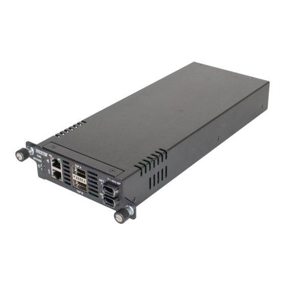
2.1 Technical and Electrical Specifications Dimensions (WxDxH): 120 x 315 x 40 mm — 4.7 x 12.4 x 1.6 in Weight: 1360 g — 2.99 lb Power requirement: 12V 4.5A 2.2 Front View TAP A F1-40G-BP link BYPASS TAP B 1, 2 PSU1, PSU2 Status LEDs QSFP+ interfaces, accepting copper/fiber... -
Page 10: Led Functionality
2.4 LED Functionality LED FUNCTION / STATE MEANING / CONTROL PSU is operating normally Green OVP: Over Voltage Protection Fan LED Orange UVP: Under Voltage Protection PSU is operating normally Green Bypass LED Monitored appliance is down, bypass is Orange activated. -
Page 11: Accessing The F1-40G-Bp Bypass Tap
4. ACCESSING THE F1-40G-BP BYPASS TAP System access can be achieved through serial or Ethernet connection. By default, the unit network interface has DHCP enabled. For accessing the unit through the serial connection, follow these steps: Power up the unit. -
Page 12: Configuration
Type the device IP in a browser. Alternatively, connect via SSH, using the unit’s IP address. Login with the default credentials. (master:master). Modify the default admin account, if desired. Login again, using the modified username:password combination. CONFIGURATION 1. WEB ADMINISTRATION The F1-40G-BP can be administered either in CLI mode or in a graphical OS and platform independent web-based interface, called BP Manager. - Page 13 ◉ Date and time information ◉ Network details ◉ Sensors (the air temperature is measured in proximity of the fans block, the system temperature is measured within the forwarding plane chip). ◉ Temperature readings for CPU, system and external air. 1.2 Ports Management The Port Management page displays the name, link status and speed of all interfaces.
-
Page 14: Bypass Settings
1.4 Bypass Settings The Bypass page represents the heart of F1-40G-BP functionality configuration, allowing the user to custom tailor the unit’s behavior, given various environment scenarios. For more information regarding operation scenarios, please goto Operation Use Cases chapter. MANUAL BYPASS: This checkbox allows the user to force the unit to bypass the traffic regardless of other bypass related rules. - Page 15 ◉ These buttons allow the user to tailor the size of the Heartbeat custom packet. There is a minimum and a maximum size allowed. Added blocks ( ) of information to the custom packet are initially filled with “00”, which can be changed as desired. HEARTBEAT RATE: Allows the user to change the rate at which Heartbeat packets are sent to the monitored appliance.
-
Page 16: Administration
Note: Please do not unplug the power cable during the update process. ▶ The device will reboot once the installation is complete and the webpage will be reloaded. 1.5 Administration Administration page allows changing system related settings. Setup tab allows editing the administration contact details, the system date and time and the network address. - Page 17 SNMP tab allows the users to enable and configure the Simple Network Manage- ment Protocol (SNMP). SNMP v1 and v2c use a community string for authentication, sent as clear text, an approach less than ideal, security wise. This is why SNMPv3 has been developed, improving on v1 and v2c by introducing the following security features: ◉...
-
Page 18: Logs
1.6 Logs Logs page displays Bypass and System logs for the specified period. To change the period, select the desired From and Until dates, and click the View button. The displayed log files can be downloaded either individually, by clicking the Download button next to the desired file’s name, or as a single file, by clicking the Download range button. - Page 19 The following commands are available in the CLI: date_time show: Displays the date. set: Allows the user to set the date and time. factory_reset Should the system become corrupted or the main parameters need to be restored to their default values, this option resets the device to the factory state and reboots the system.
- Page 20 network settings edit: Allows the user to set the IP acquisition mode of the unit to either DHCP or STATIC. In case STATIC is selected, the user has to input the IPv4, network mask, gateway and DNS address. interface.disable: Disables the Ethernet interface. The serial management port will still be operating.
- Page 21 bypass_log.show Displays all bypass events related logs and their timestamps. show_legal_info Displays the Product Legal Information. system_log monitor: Displays all system related logs and their timestamps in real time. show: Displays all system related logs and their timestamps. snmp Allows the user to configure the Simple Network Management Protocol.
- Page 22 BEHAVIOR LEVEL ENCRYPTION METHOD AUTHENTICATION KEY USERNAME USERNAME Authentication is done using a Authentication is done using a no auth no auth ONLY ONLY username only. username only. PASSPHRASE IN PASSPHRASE IN The authentication is done using the The authentication is done using the auth auth MD5 OR SHA...
-
Page 23: Operation Use Cases
OPERATION USE CASES The following cases depict all possible functional states in which F1-40G-BP can op- erate, depending on the environment changes and its configuration. CASE 1 - NORMAL OPERATION The traffic is forwarded to the appliance and heartbeat packets are injected in the network traffic in both directions. - Page 24 CASE 3 - HEARTBEAT FAILURE, BYPASS OFF If the heartbeat packets are sent to the appliance but are not forwarded back, and the Bypass in case of heartbeat failure option is set to OFF, the FPGA will not activate the bypass feature, resulting in a link failure between Network Device A and Network Device B.
- Page 25 CASE 5 - APPLIANCE LINK DOWN, BYPASS OFF If the Appliance is unpowered or the ports are disconnected, and the In case the TAP link is DOWN option is set to OFF, the FPGA will not activate the bypass feature, resulting in a link failure between Network Device A and Network Device B.
- Page 26 CASE 7 - POWER FAILURE, BYPASS OFF If power failure occurs and In case of power failure option is set to OFF (fail close), the physical bypass circuit (optical relay) inside the F1-40G-BP will not be activated resulting in a link failure between Network Device A and Network Device B.
- Page 27 CASE 9 - MANUAL BYPASS, TAP OFF If the Manual Bypass option is set to ON but TAP Mode option is set to OFF, the physical bypass circuit (optical relay) inside the F1-40G-BP is activated. The network path between Network Device A and Network Device B remains functional, but there is no traffic forwarded to the appliance.
-
Page 28: Legal
Legal DISCLAIMER The manufacturer makes no representations or warranties with respect to the con- tents hereof and specifically disclaims any implied warranties of merchantability or fitness for any particular purpose. The manufacturer reserves the right to revise this publication and to make changes in the content thereof without obligation of the man- ufacturer to notify any person of such revision or changes. - Page 30 PROFITAP HQ B. V . - High Tech Campus 84 5656AG Eindhoven - The Netherlands sales@profitap.com www.profitap.com © 2021 Profitap — v1.7-11...
Need help?
Do you have a question about the F1-40G-BP BYPASS TAP and is the answer not in the manual?
Questions and answers