Advertisement
Table of Contents
- 1 Table of Contents
- 2 General Overview
- 3 Model Variants
- 4 Powershift Transmission
- 5 Transmission Modes
- 6 Shuttle Modes
- 7 Cab Controls
- 8 Steering Mode Selection
- 9 Joystick Controls
- 10 Connecting Attachments
- 11 Automatic Lubrication System
- 12 Rear Hitch
- 13 Maintenance
- 14 Load Cell Calibration
- 15 Load Chart
- 16 Notes
- Download this manual
Advertisement
Table of Contents

Related Manuals for New Holland TH Telehandler


Summary of Contents for New Holland TH Telehandler
- Page 1 TH Telehandler Quick Operation Guide...
-
Page 2: Table Of Contents
Contents General Overview……………………………………………………………………1 Model Variants………………………………………………………………………..2 Powershift Transmission………………………………………………………….3 Transmission Modes………………………………………………………………..4 Shuttle Modes…………………………………………………………………………5 Cab Controls………………………………………………………………….…….6-7 Steering Mode Selection…………………………………………………………8 Joystick Controls……………………………………………………………………..9 Connecting Attachments……………………………………………………….10 Automatic Lubrication System…………………………………………….…11 Rear Hitch……………………………………………………………………….…….12 Maintenance…………………………………………………………………………13 Load Cell Calibration……………………………………………………………..14 Load Chart……………………………………………………………..….….…15-16 Notes…………………………………………………………………………….……..17... -
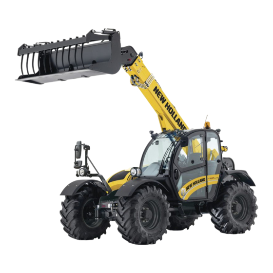
Page 3: General Overview
General Overview 1. Quick Coupler 7. Hydraulic fluid reservoir 2. First telescopic arm section 8. DEF/AdBlue tank 3. Second telescopic arm selection 9. Fuel tank 4. Engine compartments 10. Steps 5. Battery compartment 11. Cab door and hand holds 6. Cab... -
Page 4: Model Variants
Model Variants Reach Lift capacity Max engine power Version Model [kg] [hp] TH5.26 2600 TH6.28 6.35 2800 TH6.32 3200 S, Classic TH6.36 3600 133 or 146 Plus, Elite TH7.32 3200 S, Classic, Plus TH7.37 3700 133 or 146 Classic, Plus, Elite TH7.42 4200 133 or 146... -
Page 5: Powershift Transmission
Powershift Transmission S and Classic ▪ 4F x 3R transmission with 133hp max power engine ▪ Manual shifting Plus ▪ 6F x 3R transmission with 133hp max power engine ▪ Manual and semiauto shifting Elite ▪ 6F x 3R transmission with 146hp max power engine ▪... -
Page 6: Transmission Modes
Transmission Modes Multiple transmission mode • Plus models feature a semi-auto shifting mode suitable for road work • Elite models offer a semi-auto mode for short cycle job and a full-auto mode for long cycle and road work. PLUS Manual Semi-Auto 1 ↔... -
Page 7: Shuttle Modes
Shuttle Modes To change shuttle modes follow this quick step by step guide. Press and hold enter button until “SETUP MENU” is displayed Use UP/DOWN button to navigate to the transmission symbol shown in display Toggle between modes 1,2 and 3 and select any one needed by pressing enter. -
Page 8: Cab Controls
Cab Controls S, CLASSIC and PLUS Joystick ELITE Joystick 1. Forward/Reverse Shuttle 4. Foot Throttle 2. Steering wheel 5. Machine Display 3. Foot Brake Pedal 6. Joystick... - Page 9 Cab Controls 5 14 1. Display navigation switch 9. Front working lights (enter/home) 2. Display navigation switch (up/down 10. Rotating beacon switch (optional arrow key) for all models) 3. Battery isolator switch 11. Roof wiper motor switch 4. Auxiliary hydraulic lock/enable 12.
-
Page 10: Steering Mode Selection
Steering mode selection Steering geometry selector NOTE: before selecting one of the three possible steering positions, bring the four wheels into alignment, i.e. in the straight-ahead position where symbols (1) and (2) will illuminate. NOTE: always select the two-wheel steering mode when driving on road. The steering mode selector is a three stable positions rotary switch on the right-hand side console which allows... -
Page 11: Joystick Controls
Joystick Controls Joystick for S, Classic and Plus models. Lower the boom Raise the boom Rollback the loader/attachment Dump the loader/attachment • The button (1) allows the operator to downshift the gear. • The button (2) allows the operator to upshift the gear. -
Page 12: Connecting Attachments
Connecting Attachments Make sure the hydraulic licking pins are in the unlocked position (1). Lower the boom. Position the machine so that the boom is parallel with the rear of the attachment. Rotate the headstock forward. Once lined up with the attachment lift the boom and tilt back the headstock. -
Page 13: Automatic Lubrication System
Automatic Lubrication System Telehandlers can be equipped with a centralized lubrication system, that delivers controlled amounts of grease to multiple locations on the machine through the use of pumps connected by high pressure hoses. The automatic lubrication system is split in two different and independent systems: System supported by pump with integrated control unit (1) that greases lubrication points of the machine. -
Page 14: Rear Hitch
Rear Hitch The telehandler can come specified with a rear hitch equipped with hydraulic and electric connections. The telehandler for the UK comes equipped with a pick-up hitch which is controlled from the cab. To release the hitch a latch must be released which is located under the armrest and then use the third function hydraulic service to lift/lower the hitch. -
Page 15: Maintenance
Maintenance Carry out maintenance as required by the manufacturer. In order to keep the machine in good working order, we advise you to have it checked regularly by your dealer. Before starting the machine, check daily the fluid levels of: •... -
Page 16: Load Cell Calibration
Load Cell Calibration It is very important to ensure a load cell calibration is performed at least once per year. To Enter Calibration Mode proceed as follows: • Key ON • Within 5 seconds push both switches the same time as shown in the picture •... -
Page 17: Load Chart
Load Chart Load chart for pallet forks with load at 500mm. - Page 18 Load Chart Load chart for bucket.
-
Page 19: Notes
Notes... - Page 20 This guide is not a replacement for the Operators Manual. If at any time additional assistance is required you are advised to consult the Operators Manual or you authorised New Holland Dealer February 2020...
Need help?
Do you have a question about the TH Telehandler and is the answer not in the manual?
Questions and answers