Table of Contents
Advertisement
Quick Links
Advertisement
Table of Contents

Related Manuals for BNC User Manual


Summary of Contents for BNC User Manual
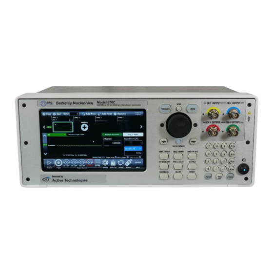
- Page 1 Simple AFG User Manual Model 670C Performance Arbitrary Waveform Generator...
-
Page 2: Table Of Contents
Table of Contents GENERAL SAFETY SUMMARY ..........................6 ..........................6 VOID IRE OR ERSONAL NJURY Use Proper Power Cord ............................6 Ground the Product ............................... 6 Observe All Terminal Ratings ..........................6 Power Disconnect ..............................6 Do Not Operate Without Covers ..........................6 Do Not Operate With Suspected Failures ....................... - Page 3 INSTRUMENT OVERVIEW ............................. 21 ................................21 RONT ANEL Analog Outputs..............................21 Marker Output Connector (670C-2C only) ......................21 Trigger In Connector (670C-2C only) ........................21 Soft keyboard and rotary knob ..........................22 Numeric Keypad ..............................23 ................................24 ANEL Marker Output Connector (670C-4C only) ......................25 Trigger In Connector (670C-4C only) ........................
- Page 4 ..................................61 WEEP Sweep Mode ................................ 61 Parameters ................................62 Sweep Trigger Mode ............................62 Marker Out behavior in Sweep Run Mode ......................62 ..................................64 URST Burst Mode ................................64 Marker Out behavior in Burst Run Mode ......................67 CHANNELS AND DEVICE SETTING ..........................
- Page 5 INSTRUCTION MANUAL, Model 670C © Copyright 2016-2023, by BNC San Rafael, CA, USA. All rights reserved. Model 670C Berkeley Nucleonics Corp. 5 of 88...
-
Page 6: General Safety Summary
General Safety Summary Review the following safety precautions to avoid injury and prevent damage to this product or any products connected to it. To avoid potential hazards, use this product only as specified. Only qualified personnel should perform service procedures. To Avoid Fire or Personal Injury Use Proper Power Cord Use only the power cord specified for this product and certified for the country of use. -
Page 7: Safety Requirements
Safety Requirements This section contains information and warnings that must be observed to keep the instrument operating in a correct and safe condition. You are required to follow generally accepted safety procedures in addition to the safety precautions specified in this section. Safety Symbols Where the following symbols appear on the instrument’s front or rear panels, or in this manual, they alert you to important safety considerations. - Page 8 CAUTION The CAUTION sign indicates a potential hazard. It calls attention to a procedure, practice or condition which, if not followed, could possibly cause damage to equipment. If a CAUTION is indicated, do not proceed until its conditions are fully understood and met. WARNING The WARNING sign indicates a potential hazard.
-
Page 9: Environmental Considerations
Environmental considerations Product End-of-life Handling Observe the following guidelines when recycling an instrument or component. Equipment Recycling Production of this equipment required the extraction and use of natural resources. The equipment may contain substances that could be harmful to the environment or human health if improperly handled at the product’s end of life. -
Page 10: Preface
Preface This manual describes the installation and operation of Model 670C Series using the Simple AFG software. Basic operations and concepts are presented in this manual. The easiest touch screen display interface allows to create waveforms scenarios, only in few screen touches. -
Page 11: Recommended Accessories
Recommended Accessories Note Item Description Used in TrueArb mode only 670C-DIG8 8 channel Digital license (Mini SAS cable included) Used in TrueArb mode only AT-DTLL8 LVDS to LVTTL digital adapter probe Used in TrueArb mode only AT-LVDS-SMA8 LVDS to SMA digital adapter cable 670C-WAR 3 years warranty extension for 670C 670C-HV... -
Page 12: Key Features
Key features The following list describes some of the key features of the Model 670C Series • High resolution, high sampling rate: 16 Bits, 600MS/s • Best output frequency vs amplitude trade off: up to 180MHz, up to 12V voltage window •... -
Page 13: Environmental Requirements
Environmental requirements Before using this product, ensure that its operating environment is maintained within these parameters: Temperature Operating +5°C to +40°C (+41°F to 104°F) Non-operating -20°C to +60°C (-4°F to 140°F) Humidity Operating 5% to 80% relative humidity with a maximum wet bulk temperature of 29°C at or below +40°C, non-condensing. -
Page 14: Calibration
Inspect the arbitrary waveform generator as often as operating conditions require. To clean the exterior surface, perform the following steps: • Remove loose dust on the outside the instrument with a lint-free cloth. Use care to avoid scratching the front panel display. •... -
Page 15: Installing Your Instrument
Installing your instrument Unpack the instrument and check that you received all items listed in the Package Content paragraph. Power the Instrument On and Off and Launch AFG Application Power On • Insert the AC power cord into the power receptacle on the rear panel. •... -
Page 16: Protect Your Instrument From Misuse
Protect Your Instrument from Misuse Check Input and Output Connectors When connecting a cable, be sure to distinguish the input connector from the output connectors to avoid making the wrong connection (images are referred to 670C-2C/4C models). CAUTION. Do not short output pins or apply external voltages to Output connectors. The instrument may be damaged. -
Page 17: Obtaining The Latest Version Releases
Obtaining the Latest Version Releases The latest release of the software may not be installed on your instrument. The latest version could be found on Berkeley Nucleonics’ website (www.berkeleynucleonics.com) in the support area Install Simple AFG Application If your instrument has already installed another version of the Simple AFG application, DO NOT uninstall it otherwise you will lose all the configurations and projects. - Page 18 Model 670C Berkeley Nucleonics Corp. 18 of 88...
-
Page 19: Usb Pen Drive And Recovery Procedure
USB Pen Drive and Recovery Procedure In case of software failure or corrupted applications, it’s possible reinstall the full factory image of the software using the 32 GB Usb Pen Drive included in the package. Note: In the Recovery USB Pen Drive you’ll find the same version of applications, drivers and updates that were installed on the instrument at the time of purchase. - Page 20 3) In the Boot menu select the “UEFI: USB DISK 3.0 PMAP, partition 1” choice and then press Enter. 4) Press ‘1’ on the keyboard to start the recovery procedure. 5) Enter the code "1234" to confirm the execution of the recovery procedure. 6) Once the procedure is complete, press enter to shut down the instrument.
-
Page 21: Instrument Overview
BNC. Marker Output Connector (670C-2C only) the front panel in the 670C-2C/4C models. See “Auxiliary The Marker Out BNC connector is located on Channels” section form more information. Trigger In Connector (670C-2C only) on the front panel in the 670C-2C/4C models. See “Auxiliary The Trigger In BNC connector is located Channels”... -
Page 22: Soft Keyboard And Rotary Knob
Soft keyboard and rotary knob Most of the buttons you use with Simple AFG application are virtual ones on the touchscreen, but a few physical buttons control basic functions, such as the setting of amplitude, offset, frequency, etc. A physical numeric keypad is available on the front-panel and it can be used instead of the virtual numeric pad. -
Page 23: Numeric Keypad
Button Description HOME If you are in a sub-menu page, use this button to return to the main page. TRIGGER Use this button to send an internal trigger to the instrument. If the button is on and green the Use this button to start and stop the signal generation. instrument is running while if it is off the instrument is stopped. -
Page 24: Rear Panel
When you select a parameter on the user interface, if you press a Unit Measure Range button it will automatically update the available range allowed for that parameter. Unit Measure Range Button Unit Measure Range Tera / pico Giga / nano Mega / micro Kilo / milli For example if you select the Frequency parameter and you press k/m the unit measure range will be... -
Page 25: Marker Output Connector (670C-4Conly)
Marker Output Connector (670C-4Conly) the rear panel in the 670C-4C models. See “Auxiliary The Marker Out BNC connector is located on Channels” section for more information. Trigger In Connector (670C-4C only) on the rear panel in the 670C-4C models. See “Auxiliary The Trigger In BNC connector is located Channels”... -
Page 26: Introduction
Introduction The Model 670C instrument, when used in Arbitrary Function Generator mode, has two/four independent analog channels. Each channel can generate a predefined waveform or a user defined waveform loaded from a file. Any characteristic parameter of the selected waveform can be modified at runtime. For example, if a pulse waveform is selected it is possible to define at runtime its amplitude, offset, frequency, duty cycle and the duration of leading and trailing edge. -
Page 27: Simple Afg Software
Simple AFG Software The Model 670C includes a 7” capacitive touch screen and an easy touch user interface instrument based on a Microsoft Windows 10 platform. You can control instrument operations using one or all of the following entering methods: •... -
Page 28: User Interface Description
User Interface Description The Simple AFG software environment provides an easy access to all instrument functionalities and parameters. AFG user interface consists of four main elements: • Waveform Parameters Area: it contains all the waveform settings. It is composed by the Carrier tab and the Secondary tab. -
Page 29: Waveform Parameters Area
If you use the Swipe Up or Down gesture over the Command Bar Area you can switch between the adjacent channels. If you use the Swipe Left or Right gesture over the Command Bar Area you can switch between the Tab Section. Waveform Parameters Area This section is composed by two tabs: the Carrier tab and the Secondary tab. - Page 30 You can touch the parameter area to open the Virtual numeric keypad, edit the parameter value and its measure unit. Below there is a description of the keypad items: Model 670C Berkeley Nucleonics Corp. 30 of 88...
- Page 31 1. Parameter Name and Value: This area of the virtual keyboard displays the parameter name, value and unit of measure. 2. Numeric Keypad: this area contains the keys to edit the number that will be displayed in the area 1. The [+/-] key will toggle the sign of the number being entered and can be pressed at the end of the number editing.
-
Page 32: Graph Area
Graph Area The graph area displays the Output channel waveform with a vertical legend that shows the minimum and maximum voltage levels and the offset. When View All Channels is checked the graph shows all channels graphs overlapped. The vertical scale is referred to the most amplitude from the channels. -
Page 33: Zoom Graph
Zoom graph Tapping on the highlighted button below, you can open another panel with more functions that expands the functionality of the graph. In particular, this new panel give you the possibility to Zoom into area of the graph with different modality. - Page 34 out, one finger to translate window zoom left or right, otherwise you can select a rectangle area if the correct button is enabled. Every time that you Zoom In, will be add to a stack the previous value of Zoom and will be show two buttons, “Reset” and “Back” in the command bar, these buttons permit you to come back the previous values or set the default value state of the waveform with zoom at 100%.
- Page 35 You can decide to View only the channels that you want tapping on colored buttons under the graph. 3. Times Scale: if enabled the Times Scale is visible, otherwise Samples Scale by default. 4. View Grid: if enabled, you can view further horizontal e vertical line with an others value of amplitude and Samples/Times.
- Page 36 5. Zoom Rect Area: if enabled, the multitouch and the translation left/right will be disabled, you can holding down and then release to select an area to Zoom. 6. Cursor: enable this button if you want to see a cursor on the graph that visualizes the values (Sample/Time and Amplitude) of the waveforms in the position set.
- Page 37 7. Info Buttons: tap to open a panel where they are indicated a lite description of the buttons just listed. Model 670C Berkeley Nucleonics Corp. 37 of 88...
-
Page 38: Channel Information
Channel Information This area displays the channel name and a list of all the main current channel settings: the selected waveform type, the Modulation / Sweep / Burst mode, the Generation mode, the channel status and the Trigger Source. Command Bar Area The command bar contains several touch buttons to control the instrument. - Page 39 Wave. List Button – Use this button to open the page where you can import a waveform from a file and use it as Carrier Waveform, Modulation Law or Sweep Profile. (For more information, please refer to the relative section). Default –...
- Page 40 About Button – Use this button to check the credits, the software and firmware release number and the instrument serial number. Help Button – Use this button to open the User Manual. Calibration button – Use this button to enter the Calibration and Diagnostic page.
-
Page 41: Input / Output Channels
The 670C instrument has two or four independent analog channels. Each channel is a single-ended output and it is provided on a BNC connector located on the front instrument panel (CH 1 OUTPUT, CH 2 OUTPUT and CH 3 OUTPUT, CH 4 OUTPUT). - Page 42 Amplitude The amplitude can be represented in three different formats that can be selected by opening the menu beside the amplitude label: • Vpp (Peak to Peak Voltage): it is the difference between the highest and lowest level of the waveform.
- Page 43 The amplitude and the offset can be represented in four different formats, as listed before, that can be selected by rotate the 3D cube as below: Model 670C Berkeley Nucleonics Corp. 43 of 88...
- Page 44 Model 670C Berkeley Nucleonics Corp. 44 of 88...
- Page 45 Frequency [Hz] / Period [s] This parameter defines the frequency or the period of the generated waveform. This parameter is available for all the functions except DC Level and Noise. In sweep run mode it is replaced by the Phase[deg] or Start Freq./Stop Freq. [Hz] parameters. Rotating the parameter (in the same way as amplitude parameter) the format switches between Frequency and Period.
- Page 46 Note: Using the Pulse Waveform the following constraints must be met: ������������ �������� + �������������� �������� < ������������ ��������ℎ < ������������ Model 670C Berkeley Nucleonics Corp. 46 of 88...
-
Page 47: Auxiliary Channels
Run Mode. To set the Marker Out parameters refer to the Channel Settings. Marker Out Specification Value Connector 1 BNC on the Front Panel (model 670C-2C) or 1 BNC on the Rear Panel (model 670C-4C) 50Ω Output impedance Output level (into 50 Ω) -
Page 48: Reference Clock Input
Trigger In signal (blue, top) that starts a burst of sine waveform (red, bottom) Reference Clock Input The 670C instrument can use an external clock source to generate the sampling clock frequency. This feature allows to synchronize the generator with an external clock. The connector type is a SMA. -
Page 49: Predefined Waveforms
Predefined Waveforms The Simple AFG application provides 13 predefined functions each of them described by its own set of parameters. It is also available the Arbitrary waveform that allow to load a waveform from a file or from remote. Touching the “Waveform” button on the “Carrier” a dropdown menu opens where it is possible to select a waveform to use as carrier. - Page 50 Waveform Frequency Range Parameters Sweep Burst PSK, Sine Models 670C-2C & 670C-4C: Amplitude, Offset, √ √ √ 1 uHz÷150 MHz ≤ 6Vpp Frequency, Phase 150 MHz÷180 MHz ≤ 5Vpp With HV option: 1 uHz÷50 MHz ≤ 12Vpp 50 MHz÷60 MHz ≤ 10Vpp 60 MHz÷100 MHz ≤...
- Page 51 Waveform Frequency Range Parameters PWM Sweep Burst PSK, Pulse Amplitude, Offset, Models 670C-2C & 670C-4C: Frequency, Phase, Duty √ √ 1 uHz÷80 MHz ≤ 6Vpp Cycle, Leading Edge, With HV option: Trailing Edge 1 uHz÷3 MHz ≤ 12Vpp 3 MHz÷10 MHz ≤ 11Vpp 10 MHz÷70 MHz ≤...
- Page 52 Waveform Frequency Range Parameters Sweep Burst PSK, Gaussian All models: Amplitude, Offset, 1 uHz÷10 MHz ≤ 6Vpp √ √ √ Frequency, Phase With HV option: 1 uHz÷10 MHz ≤ 12Vpp Lorentz All models: Amplitude, Offset, 1 uHz÷10 MHz ≤ 6Vpp √...
- Page 53 You can assign the “Arbitrary” waveform using the combo box highlighted in figure below (refer to “Waveform List” description paragraph): Note: When Arbitrary waveform is selected the amplitude and offset of the original waveform are lost because the waveform in normalized. Anyway, the amplitude and offset of the normalized waveform can be modified as for any predefined waveforms.
-
Page 54: Run Mode
Run Mode On the Carrier tab pressing the “Run Mode” button a menu opens showing all possible choices for the Run Mode. If “Modulation”, “Sweep” or “Burst” is selected the software moves directly on the secondary tab that takes the name of the selected Run Mode. Note: after enabling a channel and pressing the Running button (see Command Tool Area section), the generation of the corresponding waveform will start keeping the first sample of the waveform constant for about 200ns. -
Page 55: Continuous
Continuous In the Continuous mode when the Run/Stop button is pressed the waveform is reproduced continuously until the Run/Stop button is pressed again or Waveform / Run Mode is changed. Model 670C Berkeley Nucleonics Corp. 55 of 88... -
Page 56: Marker Out Behavior In Continuous Run Mode
Marker Out behavior in Continuous Run Mode In Continuous mode, the Marker Out generate a pulse with a duty cycle of 50% at the beginning of each period. The Marker have the same frequency of the carrier waveform until it is below 75MHz. Over 75MHz the Marker Out frequency is divided by 4 from 150MHz up to 180MHz (only for models 670C-2C &... -
Page 57: Modulation
Modulation In this Run Mode, it is possible to modulate a carrier waveform with a modulation law that can be another waveform or an external signal. All waveforms except Noise and DC level support the Modulation Run Mode. Touching the “Mod.Type” button the modulation type menu opens as shown in the picture below. With the button Hide Profile you can view and hide the waveform modulation profile on the graph The modulation types are: •... -
Page 58: Marker Out Behavior In Modulation Run Mode
Touching the “Mod.Wave” button the modulation type menu opens. The possibility to choose the shape is only available for AM, FM, PM and PWM modulations. The modulation Shapes (when available) can be: • Sine • Square • Triangle • Increase Ramp •... -
Page 59: Modulation General Parameter
Modulation General Parameter • Frequency [Hz]: it defines the modulating frequency. It can vary between 500uHz and 48MHz. Modulation Types and associated parameters • Amplitude Modulation (AM): the amplitude of the carrier waveform is modulated following the modulating shape. It is available except for the Noise, DC Level, Pulse and Double Pulse function. The parameter Depth [%] controls the modulation depth between 0% and 120%. - Page 60 ���������������� �������� [ �� ] 100 [ % ] ������������������ [ % ] ≤ 100 [ % ] − �������� ���������� [ % ] − ∗ − �� ������������ [ �� ] Where ε is a small margin to avoid that the duty cycle reaches the 0 % or the 100 % and the factor “0.8”...
-
Page 61: Sweep
Sweep The Sweep mode varies the waveform frequency following a law that can be Linear, Logarithm, Upstair or User Defined. The User Defined selection gives the possibility to load the sweep profile from a file. The Sweep is available for all function except for Pulse, Double Pulse, Noise and DC level. Sweep Mode Touching the Sweep Mode button, a menu opens that gives the possibility to choose a sweep profile among the following:... -
Page 62: Parameters
• Upstair: the frequency varies step by step. The number of steps is selectable through the Step Number parameter. • Arbitrary: allows to load a sweep profile from a file. By default, the “Arbitrary” waveform is a cosine function. As Carrier Arbitrary you can select the waveform by combo box Waveform List. Note: the time to execute the sweep is the sum of Rising, Holding and Falling Time. - Page 63 Marker out (blue, top) synchronous with the sweep (red, bottom) Model 670C Berkeley Nucleonics Corp. 63 of 88...
-
Page 64: Burst
Burst In Burst mode a waveform is repeated a predefined number of times or until the Trigger signal is at High Level depending on the selected Burst Type. This Run Mode is available for all waveforms except the DC level. Burst Mode The burst mode allows to define the behavior of the instrument after the Trigger reception. - Page 65 “false” the instrument terminates the current burst sequence then it returns waiting for the next trigger. In Gated mode, if the source of trigger is external (from connector BNC Trigger In), a trigger condition is “true” when it crosses the selected Threshold with the selected Edge, otherwise it’s “false”...
- Page 66 Note: after the execution of the each burst the Output voltage level keeps the Last Sample voltage (equal to the First sample) of the carrier waveform. This is true except for Exponential Rise, Exponential Decrease and Arbitrary Carrier where the Wait Trigger On parameter is enabled: In this case the user can set which voltage level will be generated between one burst and another: the carrier’s first or last sample.
-
Page 67: Marker Out Behavior In Burst Run Mode
Marker Out behavior in Burst Run Mode In this Run Mode, the Marker Out generates a pulse with a duration equal to the duration of the burst sequence or to the gate time duration (time when the Trigger signal is at High level). Es.1: in the following picture the gated mode operation is shown. -
Page 68: Channels And Device Setting
Channels and Device Setting Channels Settings Touching the Setting Tab or slide left right until you reach the setting page. The parameters present in Channel settings are descripted in the table below: Channel Setting Description Initial Delay [s] Set the Initial Delay of the selected channel. The delay range is 0s to 14 s. Load Impedance The instrument applies the appropriate scaling to the output waveform to get the [Ohm]... -
Page 69: Settings Button
Low Limit [V] Sets the minimum voltage that the channel generates. This limit is verified during the generation. The constraint Low Limit < High Limit must be met. This feature can be used to ensure the load is not damaged. Note: The Low Limit doesn’t force setting voltages under the limit, but during the generation the part of the waveform that exceeds the limit will be cut at the Low Limit. - Page 70 Timing Setting Description If Internal Clock is selected, the internal DAC sampling clock is synthesized Clock Source using a 10Mhz reference clock generated internally. If the external Reference Clock In (External Clock) is selected, the DAC sampling clock is synthesized using the clock provided externally to the Ref.Clock In SMA connector on the rear pannel of the instrument.
-
Page 71: Trigger Settings Tab
Source is Timer. The Interval range is from 13.4ns to 100s. The edited value is automatically rounded to the closest value that the hardware can implement. It is the threshold that the external signal applied to the “Trigger In” BNC Threshold [V] connector must cross to issue a Trigger event to the instrument. -
Page 72: Marker Settings
Ohm. Marker Settings The Marker Out settings parameters are located in the Marker Settings tab. The MARKER OUT BNC connector is shared by each channel of the instrument but it’s possible to link the marker signal coming out of it to a predetermined one. - Page 73 Marker Skew [s] It sets the delay between the marker and the analog channel. This (Run Mode Contin. or parameter is valid only if the run Continuous Mode or Modulated Mode Modul) or Sweep Repeated Mode is been selected for the associated channel to the Marker out.
-
Page 74: Main Command Button Description
Main Command Button Description Save As... A configuration can be saved by means of the “Save As” button that will open the following dialog box. The configuration will be saved in the configuration list that can be accessed by the “Load From” dialog box: In this page you can add a new configuration entry or overwrite an existing one. -
Page 75: Remote Control
In the “Load From” page it is also possible to manage the configuration list: you can delete, import or lock a configuration. When a configuration is locked it can’t be deleted or overwrited. If you touch the Import Configuration button you can import the configuration file that comes from a different machine or from a different user. -
Page 76: Remote Desktop Connection
In the top of the page the Host Name and the IP Address of the instrument are shown. The slider on the right side of the page allows to enable or disable the SCPI server. It is enabled by default. Remote Desktop Connection The following credentials must be used when connecting to the instrument by a remote desktop connection:... -
Page 77: Waveform List
Waveform List By pressing the button the Waveform List page will open showing all the waveforms available in the current configuration. The Model 670C contains by default a set of Factory Predefined Waveforms. The Predefined Waveforms are the ones in red color on the list, the imported waveforms are the ones in gray. -
Page 78: How To Import A Waveform From A File
How to import a waveform from a file Import button allow you to import data from a file to create a new waveform. The supported file formats are: • .txt – New line (\n) separated text file (one column only with no header) •... -
Page 79: How To Edit A Waveform
Select a waveform on the waveform list. • Press the button to launch the “Waveform Editor”. • Please refer to the “Waveform Editor” user manual for a complete explanation about editing and creating waveforms. How to create a new Waveform • Prerequisites: “Waveform Editor” software installed. -
Page 80: Channel Coupling
Channel Coupling In electronics design and testing, you sometimes want to have two synchronized clock signals that are related by a frequency ratio; one clock needs to maintain a certain frequency ratio with the other clock. Or perhaps, you want to simulate an amplifier with an offset; the amplifier output needs to maintain a defined offset from the input amplitude. - Page 81 The Channel Coupling section allows you to specify that Channel N parameter like frequency, amplitude, offset etc. is related to Channel 1 parameter by a ratio (multiplying) and an offset (adding). The equation that specifies the relation between the Channel N parameter to the Channel 1 parameter is the following: Ch[N] Parameter = CH1 Parameter * Ratio + Offset The coupled parameters will change in real time following the changes of Channel 1 parameters to...
-
Page 82: Calibration And Diagnostic
Calibration and Diagnostic The calibration button in the More... menu opens the Calibration and Diagnostic page. Below a description of the actions executed by pressing the buttons located in the page: • Warm up button: touching this button will start the warm up instrument procedure that will take 30 minutes. -
Page 83: License
License The license button in the More... menu opens the License page that serves to manage the license options. Touching the Add New License button it is possible enter a new licence key to enable any of the following features: 670C-2C model: a. -
Page 84: Gpib And Usbtmc (With - Gpibusb Option Only)
GPIB and USBTMC (with – GPIBUSB option only) While the VXI-11 server is always available to remotely control all the parameters of the instrument, with GPIBUSB option the 670C series is provided with a GPIB electronic interface and a USBTMC port (refer to the Programmer manual for a complete description of all instrument setting commands and data transfer commands). -
Page 85: Usbtmc Control
• Set the GPIB address. A unique device address must be assigned to each device on the bus. The default setting for the GPIB configuration is Address [N] 20. If you need to change the GPIB address set it in Address [N] parameter. USBTMC control The USBTMC protocol allows USB devices to communicate using IEEE488 style messages. -
Page 86: Certifications
Certifications Berkeley Nucleonics Corp. certifies compliance to the following standards as of the time of publication. Please see the EC Declaration of Conformity document shipped with your product for current certifications. EMC Compliance EC DECLARATION OF CONFORMITY - EMC The instrument meets intent of EC Directive 2014/30/EU for Electromagnetic Compatibility. Compliance was demonstrated to the following specifications listed in the Official Journal of the European Communities: EN 61326-1:2013, EN 61326-2-1:2013 EMC requirements for electrical equipment for measurement,... -
Page 87: Environmental Compliance
EN 61010-1:2010 Safety requirements for electrical equipment for measurement, control, and laboratory use – Part 1: General requirements EN 61010-2:030:2010 Safety requirements for electrical equipment for measurement, control, and laboratory use – Part 2-030: Particular requirements for testing and measuring circuits The design of the instrument has been verified to conform to the following limits put forth by these standards: •... - Page 88 Contact Us Berkeley Nucleonics Corporation Phone: (415) 453-9955 2955 Kerner Blvd. Email: info@berkeleynucleonics.com San Rafael, CA 94901 Web: www.berkeleynucleonics.com Model Type User Manual Document Version 2.1.0 Print Code: 22022011 Model 670C Berkeley Nucleonics Corp. 88 of 88...
Need help?
Do you have a question about the User Manual and is the answer not in the manual?
Questions and answers