Advertisement
Quick Links
Advertisement

Related Manuals for BNC 670C


Summary of Contents for BNC 670C
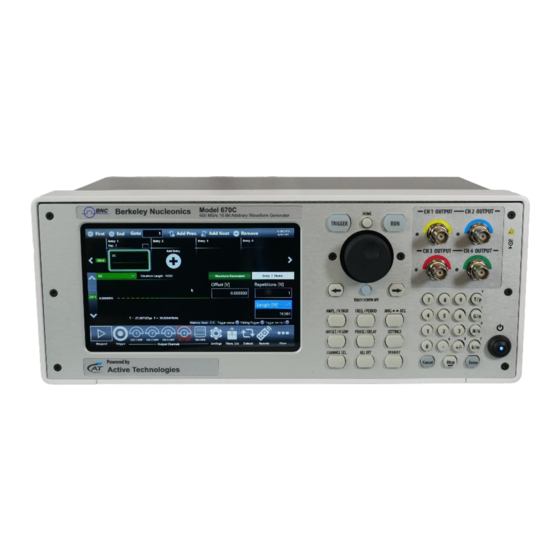
- Page 1 True ARB User Manual Model 670C Performance Arbitrary Waveform Generator...
- Page 2 N AND FF ................................ROTECT NSTRUMENT FROM ISUSE ..............................BTAINING THE ATEST ERSION ELEASES ..............................NSTALL PPLICATION ..................................USB P RIVE AND ECOVERY ROCEDURE ..............................Recovery Procedure ............................. 18 INSTRUMENT OVERVIEW ............................20 Model 670C Berkeley Nucleonics Corp. 2 of 96...
- Page 3 RONT ANEL ........................................Analog Outputs ..............................20 Marker Output Connector (Model 670C-2C only) ....................20 Trigger In Connector (Model 670C-2C only) ......................20 Soft keyboard and rotary knob ..........................21 Numeric Keypad ..............................22 ANEL ........................................Marker Output Connector (Model 670C-4C only) ....................24 Trigger In Connector (Model 670C-4C only) ......................
- Page 4 USBTMC control ..............................88 APPENDIX A – DIGITAL OPTION AND ACCESSORIES ....................89 AT-LVDS-SMA8 ............................91 AT-DTLL8 ..............................92 CERTIFICATIONS ................................94 EMC C OMPLIANCE ......................................AFETY OMPLIANCE ......................................NVIRONMENTAL OMPLIANCE ..................................Model 670C Berkeley Nucleonics Corp. 4 of 96...
- Page 5 Berkeley Nucleonics products are covered by Italian and foreign patents, issued and pending. Information in this publication supersedes that in all previously published material. Specifications and price change privileges reserved. Model 670C Berkeley Nucleonics Corp. 5 of 96...
- Page 6 If you suspect that there is damage to this product, have it inspected by qualified service personnel. Do not touch exposed connections and components when power is present. Refer to the manual’s installation instructions for details on installing the product so it has proper ventilation. Model 670C Berkeley Nucleonics Corp. 6 of 96...
- Page 7 This symbol is used to denote Power. It is located on the front panel and denotes Power On/Off status of the instrument. This symbol is used to denote Direct Current. This symbol is used to denote that the device connectors are sensitive to electrostatic discharge Model 670C Berkeley Nucleonics Corp. 7 of 96...
- Page 8 Installation (Overvoltage) Category rating per EN 61010-1 safety standard and is applicable for the instrument front panel measuring terminals. CAT I rated terminals must only be connected to source circuits in which measures are taken to limit transient voltages to an appropriately low level. Model 670C Berkeley Nucleonics Corp. 8 of 96...
- Page 9 The symbol shown to the left indicates that this product complies with the European Union’s requirements according to Directive 2002/96/EC on waste electrical and electronic equipment (WEEE). Model 670C Berkeley Nucleonics Corp. 9 of 96...
- Page 10 This manual describes the installation and operation of Model 670C Series using the Simple TrueArb software. Basic operations and concepts are presented in this manual. The easiest touch screen display interface allows to create waveforms scenarios, only in few screen touches.
- Page 11 LVDS to SMA digital adapter cable 670C-WAR 3 years warranty extension for 670C 670C-HV High voltage output (12Vpp on 50 Ohm) for 670C-2C 670C -HV High voltage output (12Vpp on 50 Ohm) for 670C-4C GPIB / USB-TMC GPIB and USBTMC Ports for Remote Control Net Weight 6.5kg...
- Page 12 The following list describes some of the key features of the Model 670C Series • High resolution, high sampling rate: 16 Bits, 600 MS/s • Best output frequency vs amplitude trade off: up to 180MHz, up to 12V voltage window •...
- Page 13 No manual voltage selection is required because the AC Adapter automatically adapts to line voltage. Source Voltage and Frequency 100 to 240VAC ±10% @ 45-66 Hz Power Consumption Maximum: 100W WARNING - Electrical Shock Hazard Only use the power cord provided with your instrument Model 670C Berkeley Nucleonics Corp. 13 of 96...
- Page 14 Proper use of the instrument depends on careful reading of all instructions and labels. WARNING Any use of the instrument in a manner not specified by the manufacturer may impair the instrument’s safety protection. Model 670C Berkeley Nucleonics Corp. 14 of 96...
- Page 15 Check Input and Output Connectors When connecting a cable, be sure to distinguish the input connector from the output connectors to avoid making the wrong connection (images are referred to 670C-4C models). Model 670C Berkeley Nucleonics Corp.
- Page 16 1. Download the Simple TrueArb setup package from Berkeley Nucleonics’ website and decompress it to instrument’s local disk. 2. Right click on the “Add-AppDevPackage.ps1” file and select Run with PowerShell to start the installation. Model 670C Berkeley Nucleonics Corp. 16 of 96...
- Page 17 3. When the application has been installed, press the “Enter” button to continue. Model 670C Berkeley Nucleonics Corp. 17 of 96...
- Page 18 Check that a keyboard is correctly connected to the instrument. 2) Once the instrument is started press repeatedly F11 button on the keyboard during the Boot process and access the Boot menu (see the image below). Model 670C Berkeley Nucleonics Corp. 18 of 96...
- Page 19 6) Once the procedure is complete, press enter to shut down the instrument. Remove the Recovery USB Pen Drive and power ON the instrument. Follow the instructions at point 2) to access the Boot menu and select SATA SSD source. Press enter to confirm. Model 670C Berkeley Nucleonics Corp. 19 of 96...
- Page 20 The Touch screen functionalities and features are described in the Simple TrueArb Application paragraph. The Model 670C Series instrument has two or four analog output channels, each one is single- ended and the connector type is a standard BNC. models. See “Auxiliary...
- Page 21 The ➔ key will move the selected digit to the right and the � key will move the selected digit to right. You can keep pressed the rotating knob and rotate it on the right or on the left to change the Delta increment. Rotary Knob Rotary Push Button Digit Selection Arrows Model 670C Berkeley Nucleonics Corp. 21 of 96...
- Page 22 After the sign and the numeric portion of the desired value have been entered, the pressing of the multiplier button applies the parameter. The Enter button closes the virtual keyboard and will apply the entered value. Model 670C Berkeley Nucleonics Corp. 22 of 96...
- Page 23 2 USB 2.0 ports HDMI port 2 USB 3.0 ports VGA Out port Marker Output 2 LAN port PS/2 Mouse & Trigger Input Audio IN/OUT Keyboard ports (670C-4C only) 3 COM ports Model 670C Berkeley Nucleonics Corp. 23 of 96...
- Page 24 The Trigger In BNC connector is located Channels” section form more information. The Model 670C Series instrument can use an external clock source to generate the sampling clock See “Auxiliary Channels” section form more information. frequency. The connector type is a SMA.
- Page 25 “Trigger”. In Continuous mode the Trigger In doesn’t have any effect. Trigger In Specification Value Connector BNC on the Front Panel for 670C-2C models BNC on the Rear Panel for 670C-4C models Number of connectors 1kΩ or 50 Ohm selectable...
- Page 26 Trigger In signal (blue, top) that starts a burst of sine waveform (red, bottom) The Model 670C can use an external clock source to generate the sampling clock frequency. This feature allows to synchronize the generator with an external clock.
- Page 27 4. Touch the settings button on the Simple TrueArb UI to open the instrument settings window 5. Select Dev. Settings ➔ General page, select Continuous as Run Mode Model 670C Berkeley Nucleonics Corp. 27 of 96...
- Page 28 8. The waveform sequencer located at the top of the application starts by default with a single entry with a sine waveform. Touch the Add Entry button to insert a new entry into the Channel1. Model 670C Berkeley Nucleonics Corp. 28 of 96...
- Page 29 Sine Waveforms. 11. Enable the output channels by pressing the CH1 and CH2 buttons located in the bottom of the application so that they are no more grayed out. Model 670C Berkeley Nucleonics Corp. 29 of 96...
- Page 30 12. Touch the Entry 1 and set the Repetition[N]=2 than touch the Entry 2 and set Repetition[N]=3. 13. You can change the Amplitude/Voltage High and Offset/Voltage Low for each entry. Model 670C Berkeley Nucleonics Corp. 30 of 96...
- Page 31 14. Press the RUN/STOP button and check the generated waveforms on the oscilloscope: the Entry 1 should be repeated two times and the Entry 2 should be repeated three times. Model 670C Berkeley Nucleonics Corp. 31 of 96...
- Page 32 The Model 670C Series instrument includes a 7” capacitive touch screen and Simple touch user interface based on a Microsoft Windows 10 platform. You can control instrument operations using one or all of the following entering methods: • Touch Screen and Front-panel soft key controls •...
- Page 33 IMPORTANT NOTE The Model 670C series has a unique sequencer for all channels. Therefor the length and repetitions of each sequencer entry are common to all output channels. In the same way all analog and digital outputs share the same sampling clock. In this way they are synchronized each other.
- Page 34 Waveform Area: It contains the Waveform Graph and the Waveform Parameters related to the selected entry. • Command Bar: in this bar there are elements to control the instrument operations, to modify the instrument settings and to manipulate waveforms. Model 670C Berkeley Nucleonics Corp. 34 of 96...
- Page 35 It is possible to modify the waveform of an entry of the sequencer by touching on the waveform graph or on the name of the waveform. A dropdown list will open showing a list of all the waveforms available in the “Waveform List” (predefined or imported). Model 670C Berkeley Nucleonics Corp. 35 of 96...
- Page 36 Output Channel page. Then the waveform can be changed by pressing the dropdown waveform list. You can change the Output Channel page also using the up/down gesture on the selected Change the Output channel page Model 670C Berkeley Nucleonics Corp. 36 of 96...
- Page 37 ► The number of Repetitions. Each entry can be repeated from 1 up to 4294967295 times or infinite times (INF button). If you touch the selection button in the entry, a second bar will open that will let you to: Model 670C Berkeley Nucleonics Corp. 37 of 96...
- Page 38 The upper warning gives is general warning that notifies this condition. Additional warnings are displayed inside the entries where the warning condition is detected. Model 670C Berkeley Nucleonics Corp. 38 of 96...
- Page 39 The Waveform Parameters area is divided in two parts. The left part contains the vertical parameters of the selected waveform in terms of Amplitude[Vpp] and Offset[V] or Voltage High[V] / Voltage Low [V]. Model 670C Berkeley Nucleonics Corp. 39 of 96...
- Page 40 It defines the difference between the maximum value and the minimum value of the waveform expressed in Volts. Offset[V] It defines the voltage of (Vmax+Vmin)/2 expressed in Volts where Vmax is the maximum level of the waveform and Vmin is the minimum level of the waveform Model 670C Berkeley Nucleonics Corp. 40 of 96...
- Page 41 In case the entry length and the waveform length are different the original waveform will be manipulated (resampled/cut/extended) to match the entry length. Model 670C Berkeley Nucleonics Corp. 41 of 96...
- Page 42 You can touch the parameter area to open the Virtual numeric keypad, edit the parameter value and its measure unit. Below there is a description of the keypad items: 1. Parameter Name and Value: This area of the virtual keyboard displays the parameter name, value and unit of measure. Model 670C Berkeley Nucleonics Corp. 42 of 96...
- Page 43 7. The horizontal scrollbar allows to change quickly the selected value. The position specifies the value between the allowed minimum and the maximum. The increment/decrement value entered by the rotary knob or by the scrollbar are applied to the instrument on the fly. Model 670C Berkeley Nucleonics Corp. 43 of 96...
- Page 44 The Trigger too fast led notifies you that the trigger event has been latched, but the trigger frequency is too high and the instrument cannot be rearmed before the completion of the previous trigger event. In this situation some trigger events may be lost. Model 670C Berkeley Nucleonics Corp. 44 of 96...
- Page 45 Wavef. List – Use this button to open a page where you can Import/Export a waveform from file. (For more information, please refer to the relative section). Default – Use this button to restore the default value of all parameters of the instrument. Model 670C Berkeley Nucleonics Corp. 45 of 96...
- Page 46 Beep – Use this button to enable or disable the beep audio signal when the user touches a button. More Button – Use this button to have access to other instrument features. These buttons are explained in the following table. Model 670C Berkeley Nucleonics Corp. 46 of 96...
- Page 47 (For more information please refer to the Waveform Editor User Manual). License button – Use this button to enter the License setup page. (For more information, please refer to the relative section). Model 670C Berkeley Nucleonics Corp. 47 of 96...
- Page 48 Device Settings, Channel Settings, Marker Setting and Sequencer Setting. The device settings are common for all the instrument and they are grouped in General settings, Timing settings and Trigger settings. General Model 670C Berkeley Nucleonics Corp. 48 of 96...
- Page 49 Burst Count[N] parameter. If you set Burst Count[N]=1 the instrument is in Single mode and the sequence will be repeated only once. Start Trigger N if burst / 1 if single Model 670C Berkeley Nucleonics Corp. 49 of 96...
- Page 50 Note: if you set Infinite repetitions on one entry, the Trigger event lets you jump to the next one. Trigger Start Trigger Trigger Model 670C Berkeley Nucleonics Corp. 50 of 96...
- Page 51 Decimation: it reduces the number of samples maintaining the waveform shape • Cut tail: it cuts the tail of the waveform reducing its size • Cut head: it cuts the head of the waveform reducing its size. Jump Mode Model 670C Berkeley Nucleonics Corp. 51 of 96...
- Page 52 It will jump always at the end of a period of the current waveform. If “Jump when all repetitions have been executed” is selected, the sequencer jumps to the selected entry after the completion of the current waveform repetitions. Model 670C Berkeley Nucleonics Corp. 52 of 96...
- Page 53 In the Device Setting ➔ General page select Advanced as Run Mode • • The sequencer page will change its standard layout and the Edit Entry button will appear in the Entry Parameters area. Model 670C Berkeley Nucleonics Corp. 53 of 96...
- Page 54 Trigger button on the menu bar or from a Remote Command. • Timer: the event is internally generated by a Timer you can set on the Settings ➔ Trigger page. Model 670C Berkeley Nucleonics Corp. 54 of 96...
- Page 55 • External: the event is generated by the signal applied externally on the BNC connector (TRIGGER IN) when it crosses the selected Threshold. Note: The Trigger buttons and the Trigger from remote command are always active, independently from the selecting Trigger Source.
- Page 56 First: the sequencer jumps to the first element in the sequence • Last: the sequencer jumps to the last element in the sequence • Item: the sequencer jumps to the selected entry index. Model 670C Berkeley Nucleonics Corp. 56 of 96...
- Page 57 Jump If Timer (123) occurs: event Output Waveform Jump to Entry 4 occurs: Repeat Jump to Next 10 times Entry (Entry 2) Repetitions Complete, Go To Entry 3 Entry 3. Entry 4. Entry 2. Model 670C Berkeley Nucleonics Corp. 57 of 96...
- Page 58 The pair of channels will move simultaneously of the applied value. The maximum allowed value is 1 clock cycle that depends on the current instrument sampling rate and the resolution is about 3 ps. Model 670C Berkeley Nucleonics Corp. 58 of 96...
- Page 59 Interval [s] textbox. Trigger In Connector: the Trigger event is generated by the signal applied externally on the BNC connector (TRIGGER IN) when it crosses the selected Threshold with the selected Slope. You can select Threshold value and Slope using the relative textbox and slider.
- Page 60 10X attenuator. You can turn on the internal attenuator to improve the output signal quality with low level signals. Model 670C Berkeley Nucleonics Corp. 60 of 96...
- Page 61 Digital Channels Page (see the picture below) to define the digital waveform sequence as for the analog channel page. IMPORTANT NOTE: enabling the digital lines will cause a decrease of resolution in the analog output channels as shown in the following table: Model 670C Berkeley Nucleonics Corp. 61 of 96...
- Page 62 Number of digital Resolution Resolution Resolution Resolution lines 670C-4C models 16 bits 16 bits 16 bits 16 bits 14 bits 16 bits 16 bits 16 bits 14 bits 14 bits 16 bits 16 bits 14 bits 14 bits 14 bits...
- Page 63 On the marker output page, you can set the behavior and parameters of the Marker signal that is provided at the front panel MARKER OUT BNC connector. Marker Mode: • Automatic: the marker has a behavior that depends on the Run Mode. In detail:...
- Page 64 Adapt to the shorter analog waveform: if this option is selected the length of an entry of the sequencer by default will be equal to the length of the shorter channel waveform, among all analog channels, assigned to the entry. Model 670C Berkeley Nucleonics Corp. 64 of 96...
- Page 65 Length[N]=1024, when you press the Run button you will get a ‘Start Failed!’ error message; in this case you have to change the entry Length[N] parameter to 16384 to run the instrument. Model 670C Berkeley Nucleonics Corp. 65 of 96...
- Page 66 • Waveform List: in this area you can scroll between all stored waveforms. The 670C series contains by default a set of Factory Predefined Waveforms that are common to all configurations. The Predefined Waveforms sport an orange line under their names, Imported Waveforms instead sport a blue underline while Parametric Waveforms sport a green underline.
- Page 67 You can also access this menu by simply holding down when operating via touch, as shown below. Model 670C Berkeley Nucleonics Corp.
- Page 68 If “Digital” is selected each data point is represented by a 32-bit unsigned integer (but only the first 8 bit are significant) where the value of each bit is transferred to the corresponding digital line (Bit 0 -> Digital Line 0, Bit 1 -> Digital Line 1, …). Model 670C Berkeley Nucleonics Corp. 68 of 96...
- Page 69 Select an imported analog or digital waveform on the waveform list • Press the button and then the button • The waveform will appear on the list in red color to show that it has been promoted to Predefined. Model 670C Berkeley Nucleonics Corp. 69 of 96...
- Page 70 The newly created parametric waveform will be by default a sine waveform, which can be later changed to other kinds of waveform. Model 670C Berkeley Nucleonics Corp. 70 of 96...
- Page 71 Waveform Type Model 670C Berkeley Nucleonics Corp. 71 of 96...
- Page 72 To do that, you need to set the characteristic parameters of a waveform type, which can be easily accessed by scrolling up and down the waveform parameters area as shown in the following image. Model 670C Berkeley Nucleonics Corp.
- Page 73 To change the employed strategy, tap the Auto Calc Options drop down button and then select the strategy that best suits your needs from the submenu. Model 670C Berkeley Nucleonics Corp. 73 of 96...
- Page 74 This comes with its drawbacks though, as a not-whole number of cycles can lead to undesired signal behaviors, like a spurious signal once analyzed in the frequency domain. Model 670C Berkeley Nucleonics Corp. 74 of 96...
- Page 75 You can directly apply those values from within the pop-up message, or note them down and manually input them. Note though that these suggestions aren’t always guaranteed to be available. Model 670C Berkeley Nucleonics Corp. 75 of 96...
- Page 76 Rise Time, Pulse Delay and one between Duty Cycle and Pulse Width. You can change between Duty Cycle and Pulse Width anytime by simply tapping on them. A Pulse type parametric waveform abides by the following model: Model 670C Berkeley Nucleonics Corp. 76 of 96...
- Page 77 While Start and Stop Frequency are straightforward, as their names imply, Sweep Mode instead lets you change between a Linear and a Logarithmic sweep. To change the Sweep Mode, you only need to tap on the Sweep Mode toggle switch, as shown in the image below. Model 670C Berkeley Nucleonics Corp. 77 of 96...
- Page 78 Sinc type parametric waveforms do not have Auto Calc, as such you’re free to customize both Length and Sampling Rate as you see fit. You can further customize its shape by changing one or both among the Peak Position and Lobe Width. Model 670C Berkeley Nucleonics Corp. 78 of 96...
- Page 79 Multitone type parametric waveforms let you create your own custom sum of different sinusoidal tones, with a maximum of 10 Tones, or less if the number of samples exceed the memory limit. Model 670C Berkeley Nucleonics Corp. 79 of 96...
- Page 80 Sampling Rate. Whilst you’re adding a tone, it may happen that you mis-enter its frequency. If you want to delete a tone you can follow two distinct routes: Model 670C Berkeley Nucleonics Corp. 80 of 96...
- Page 81 A new non parametric waveform containing the array points will be created and added to the waveform list, which you can later export and modify as you see fit. Model 670C Berkeley Nucleonics Corp. 81 of 96...
- Page 82 If you touch the Export Configuration button a proprietary binary .zip file relative to the current configuration will be exported. The exported file can be used to share configurations between different users or instruments. Model 670C Berkeley Nucleonics Corp. 82 of 96...
- Page 83 If you touch the Import Configuration button you can import the configuration file that comes from a different machine or from a different user. The imported configuration will be inserted in the “Load From” list. Model 670C Berkeley Nucleonics Corp. 83 of 96...
- Page 84 SCPI server. By default it is enabled. If you need to connect to the instrument using the remote desktop connection, you should insert the following credentials: Computer Name: AT User Name: AT Password: 1234 Model 670C Berkeley Nucleonics Corp. 84 of 96...
- Page 85 • Load Factory button: touching this button will load the factory calibration parameters. Model 670C Berkeley Nucleonics Corp. 85 of 96...
- Page 86 670C-4C -256M: memory extension to 256MSamples per channel; d. 670C-4C-HV: high voltage output (12 Vpp on 50 Ohm); b. 670C-DIG8: 8 channel digital license (8/16 digital channels available) To get the license key please contact your distributor sales representative.
- Page 87 Follow these instructions to setting up the instrument for remote communication using the GPIB (General Purpose Interface Bus) interface: • Connect one side of a GPIB cable to the GPIB port of the Model 670C (on the rear panel), and your GPIB controller on the other side. •...
- Page 88 If you are using NI-VISA software, launch the NI-MAX tool on the Client-PC. After a short time a USBTMC device will be recognize. Now you can send the SCPI commands to the Model 670C resource using the NI Visa Test Panel. Model 670C Berkeley Nucleonics Corp.
- Page 89 10120666-101LF, TE Connectivity 2198484-1) but you should take case of using the electrical connection shown below. The connection of the AT-LVDS-SMA8 cable adapter (mini-SAS HD to 16 SMA adapter cable) are also described in the table below. Model 670C Berkeley Nucleonics Corp. 89 of 96...
- Page 90 SMA Ground DO7_P DO 7_P DO7_N DO 7_P DO0_P DO 0_P DO0_N DO 0_N SMA Ground CS1 (RESERVED). Do not connect. +12Vcc SMA Ground DO6_P DO 6_P DO6_N DO 6_N SMA Ground Model 670C Berkeley Nucleonics Corp. 90 of 96...
- Page 91 DO 2_N SMA Ground SCL (RESERVED). Do not connect. SDA (RESERVED). Do not connect. SMA Ground D4_P DO 4_P D4_N DO 4_N SMA Ground D3_P DO 3_P D3_N DO 3_N SMA Ground Model 670C Berkeley Nucleonics Corp. 91 of 96...
- Page 92 The AT-LVDS-SMA8 cable adapter converts from the Mini SAS HD connector located on the rear of the instrument to 16 SMA connectors. This cable ensures the best signal integrity and flexibility required for transmitting the high-speed digital signals provided by the Model 670C generator series. Output connector...
- Page 93 Important Note: the Model 670C does not include the AT-DTLL that must be bought separately. Below the description of the TTL signal connector is provided. Output connector 20 position 2.54 mm 2 Row IDC Header Output electrical standard LVTTL Output impedance 50Ω...
- Page 94 EN 61010-2:030:2010 Safety requirements for electrical equipment for measurement, control, and laboratory use – Part 2-030: Particular requirements for testing and measuring circuits The design of the instrument has been verified to conform to the following limits put forth by these standards: Model 670C Berkeley Nucleonics Corp. 94 of 96...
- Page 95 Many countries prohibit the disposal of waste electronic equipment in standard waste receptacles. RESTRICTION OF HAZARDOUS SUBSTANCES (RoHS) This instrument and its accessories conform to the 2011/65/EU RoHS2 Directive. Model 670C Berkeley Nucleonics Corp. 95 of 96...
- Page 96 Contact Us Berkeley Nucleonics Corporation Phone: (415) 453-9955 2955 Kerner Blvd. Email: info@berkeleynucleonics.com San Rafael, CA 94901 Web: www.berkeleynucleonics.com Model Type User Manual Document Version 2.2.0 Print Code: 32028270 Model 670C Berkeley Nucleonics Corp. 96 of 96...
Need help?
Do you have a question about the 670C and is the answer not in the manual?
Questions and answers