
Related Manuals for BNC 6040


Summary of Contents for BNC 6040
- Page 1 Instruction Manual Model 6040 Universal Pulse Generator 2955 Kerner Blvd. Ste D. San Rafael, CA 94901 Ph: 415-453-9955 Fx: 415-453-9956 www.berkeleynucleonics.com...
- Page 2 WARRANTY Berkeley Nucleonics Corporation warrants all instruments, including component parts, to be free from defects in material and workmanship, under normal use and service for a period of one year. If repairs are required during the warranty period, contact the factory for component replacement or shipping instructions.
-
Page 3: Table Of Contents
CONTENTS Page SECTION 1 SPECIFICATIONS Model 6040 Mainframe Characteristics Status Byte Summaries SECTION 2 OPERATING INFORMATION General Power Up LCD Power On Sequence Module Installation Warm Up Requirements Safety Precautions Electrical Cables, Attenuators and Oscilloscopes Troubleshooting LCD Contrast Cold Boot... - Page 4 CONTENTS Menus and Parameter Selection Modifying Parameters Numeric Data Entry Parameter Scanning Saving the Panel Setting in Memory Control Key Descriptions Menu Keys Memory Keys Scan Keys Function Keys Miscellaneous Keys Numeric Key Descriptions Remote Programming Initial Bus Parameter Selection Command Set Status Commands Panel Control Commands...
- Page 5 1 ns Width 10 ns Width SECTION 5 PARTS LIST AND SCHEMATICS Parts List Timing Board, 6040-2 Microprocessor Board, 6040-3 Power Supply Board, 6040-1 Annunciator Board, 6040-6 Miscellaneous Front Panel Assembly Miscellaneous Top Assembly Schematics Please contact factory for copies. July 2020...
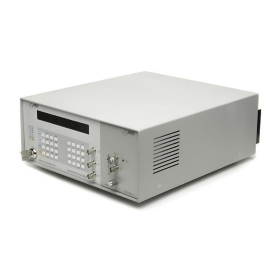
- Page 6 CONTENTS ILLUSTRATIONS Figure No. Page Frontispiece Model 6040 Universal Pulse Generator 6040 Trigger and Output Pulse Timing 6040 Timing Circuits Microprocessor Block Diagram Simplified Interconnection Diagram TABLES Table No. Instrument Status Byte Error Status Byte 6040 Mainframe Default Settings Menu Keys...
- Page 7 SAFETY PRECAUTIONS The following warnings, which appear both here and in the main body of the test, are to alert the user of potential safety hazards and to encourage safe operating practices. WARNING: To avoid possible electric shock, observe the following: Do not operate with the cover removed.
- Page 8 The Model 6040 System consists of a crystal-controlled programmable pulse/digital delay generator mainframe and a family of optional plug-in modules. The 6040 itself generates TTL and ECL outputs at rates to 100 MHz with 1 ns or less rise times and a 1 nanosecond resolution for pulse width, delay and double pulse timing.
-
Page 9: Specifications
SECTION 1 SPECIFICATIONS MODEL 6040 MAINFRAME CHARACTERISTICS Timing Characteristics INTERNAL REP RATE 0.01 Hz – 100 MHz Range: Resolution: 4 digits Accuracy: 0.01% DELAY 0 – 640 s. Range: Resolution: 1 ns or 5 digits, whichever is greater. Jitter (rms): 25 ps or 0.01% of Delay, whichever is greater. - Page 10 MODULE DISABLE Allows the outputs on some modules to be remotely disabled. Disable: 4 V - 5 V. 5 mA sourcing current (into the 6040) or contact opening. Enable: 0 - 300 mV, 5 mA sinking current (from the 6040) contact closure, or plug removed from jack.
- Page 11 IMPULSE Single Impulse: A sub-nanosecond pulse of fixed width and amplitude, with rate and delay controlled by the 6040 mainframe. Double Impulse: A pair of Identical impulses separated by the selected delay. Provides a steady-state, adjustable power level.
- Page 12 SPECIFICATIONS Programming GPIB IEEE-488 Remote interface with all functions and parameters programmable and bus triggerable. Interface Functions: SH1, AH1, T6, TE0, L4, LE0, SR1, RL1, PP0, DC1, DT1, RS-232 Remote interface with all functions and parameters programmable in full or half-duplex to 1200 baud and bus triggerable.
-
Page 13: Status Byte Summaries
SPECIFICATIONS RECALL Stored settings can be manually recalled or bus transferred to the mainframe. The setting in memory 0 is activated automatically upon power-up or reset. General DIMENSIONS 3.75" W x 4.9 " H x 10" D (95 mm x 124 mm x 254 mm). - Page 14 SPECIFICATIONS Table 1-3. Error Status Byte Description Always zero Always zero Always zero Always zero Always zero Always zero Overrange Unrecognized command Module Status Byte The Module Status byte is module dependent. Refer to the module's instruction manual. July 2020...
-
Page 15: Section 2 Operating Information
Remote Enabled LCD Power On Sequence When the 6040 is first turned on, the display will show the software version number. If a module is present, the LCD will then momentarily display "MEMORY CHECK," followed by the module I.D. display. Without a module, the display will read "6040 No Plug-In."... -
Page 16: Module Installation
OPERATING INFORMATION Module Installation CAUTION: The module must be installed with mainframe power off. A module can be damaged or have its memory corrupted if inserted or removed from the mainframe with the power on. To install a module, turn the power off, slide the module in and tighten the mount screw knob. Warm Up Requirements The instrument should be allowed to warm up for 30 minutes before high precision measurements are made. -
Page 17: Troubleshooting
Quick Test Since the 6040 uses a modular approach, operating problems can arise from either the mainframe unit or the installed module: the problem must be localized to one or the other. To test the mainframe, turn the power off, remove the module, and switch the power back on. -
Page 18: Gpib And Rs-232 Problems
The default address is 6. but may be set between 1 and 30. The 6040 will respond to remote commands only if the Remote Enable line (REM) is asserted. When this happens the LCD will display "GPIB Remote Mode," and all keys except LOCAL will be disabled. -
Page 19: Front Panel Description
WARNING: To remove all ac power from the unit, the line cord must be unplugged. LCD Display The 6040 has a 20-character liquid crystal display (LCD). This displays all menus and data while the unit is being programmed from the front panel. In the following descriptions the display for each menu is given. -
Page 20: Control Keypad
Single Pulse and Double Pulse operation. Connectors There are three BNC connectors on the front panel. These are used in the Pulse and Impulse Modes to monitor or trigger the pulse generator. PULSE OUT provides waveform synchronized to TRIG OUT. The time position (with respect to TRIG OUT) and duration of this output are set by the Delay and Width, respectively. -
Page 21: Plug-In Module Receptacle
OPERATING INFORMATION Plug-In Module Receptacle The plug-in module receptacle is on the right side of the front panel, and accepts a single BNC 6040 plug-in module. The receptacle consists of an alignment guide, one 40-pin edge connector, and one ConheX coaxial connector. -
Page 22: Reset Button 115 V/ 230 V Selection Switch And Fuse
General Menus and Parameter Selection The front panel control of the 6040 has been optimized for ease of use and understanding. The control and modification of the operating Mode, states and parameters are realized by a set of control keys. -
Page 23: Modifying Parameters
OPERATING INFORMATION The MODE and TRIG menu keys change the operating state of the 6040 directly. As the user sequences through the Mode menu, the state of the module's output is modified in accordance with the displayed Mode (Pulse, CW, etc.). Similarly, as the user sequences through the Trigger menu, the Trigger source for the pulse generator is set in accordance with the display (Internal, External, Single Cycle). -
Page 24: Numeric Data Entry
OPERATING INFORMATION Numeric Data Entry To enter an entirely new value, simply type in the desired value using the digit, decimal point, sign (where appropriate), and exponent keys, and then use either the EXEC (execute) or ENTER key to terminate the data entry. During the entry of values any errors can be corrected using the BK SPC (backspace) key. -
Page 25: Parameter Scanning
OPERATING INFORMATION Parameter Scanning The second method of altering a parameter is incremental. First display the desired parameter. Then choose the desired digit with the cursor using the left {} and right {} keys. Once the digit is selected, the increment {} and decrement {} keys allow the incremental modification of the existing value. In addition, the value will be multiplied (or divided) by ten if the left (or right) key is pressed when the cursor is located at the most (or least) significant digit. -
Page 26: Control Key Descriptions
Mode. Note that not all Modes and not all menu selections apply to each module (the appropriate module manuals provide details on this). Table 2-3 gives a list of the menu selections available for the 6040 when used as a stand alone instrument (without a module installed). - Page 27 OPERATING INFORMATION Table 1-6. Menu Keys For Stand Alone Operation MODE Menu Pulse TRIG Menu Single Cycle Internal Trigger (and Rate) External Trigger (and Threshold) External Trigger Slope TIMING Menu Delay Width Single/Double Pulse LEVEL Menu (not used) GPIB/RS-232 Menu IEEE-488 Address Baud Rate Full/Half Duplex...
-
Page 28: Menu Keys
OPERATING INFORMATION Menu Keys {MODE} Sequences through the Mode menu and determines the type of output waveform produced. The selections are Pulse, Impulse. CW. and External Modulation. These are all module dependent. With no plug-in module. Mode defaults to Pulse. Pulse Mode provides flat topped pulses from the mainframe outputs (PULSE OUT and ECL OUT) and the module output jacks(s). - Page 29 OPERATING INFORMATION {TRIG} Sequences through the trigger source and parameter menu. This is used in the Pulse and Impulse Modes. The selections are Internal Trigger, External Trigger (threshold and slope). External Drive, and Single Cycle. With no plug-in module, this is set to Single Cycle at power-on.
- Page 30 OPERATING INFORMATION Delay controls the time interval from the TRIG OUT pulse to the mainframe (PULSE OUT and ECL OUT) or module outputs. In Single Pulse operation, Delay specifies the interval between the leading edge of the TRIG OUT signal and the leading edge of the output pulse or impulse (plus a fixed delay— see Figure 1-1).
-
Page 31: Memory Keys
900 or 1200. Full Duplex/Half Duplex determines whether characters will be echoed back through the RS-232. With Full Duplex, each character sent to the 6040 will be echoed back; for Half Duplex no echoing takes place. The selection of full or half is made with the {+/-, SGL/DBL) key, which toggles between the two. -
Page 32: Scan Keys
OPERATING INFORMATION {STORE} Allows the storage of the present machine state in one of ten (nonvolatile) memory locations in the module. This is operable only with a plug-in module installed. Front Panel Display: < Store Set (0-9): i > < Stored as Set i >... -
Page 33: Numeric Key Descriptions
OPERATING INFORMATION Note: This display appears only on the return to local from remote operation. Also, under GPIB operation, the bus command LLO can disable this key. Numeric Key Descriptions The following is a detailed description of each key on the numeric keypad. {0}...{9} The digits zero through nine. -
Page 34: Remote Programming
Extra blank spaces are ignored. Error messages, sent back by the 6040 in response to invalid commands or data, are listed in Table 2-4. In all of the commands listed here, i represents an integer value, f, v, and x may be in integer, floating point, or exponential notation, and c represents an ASCII character string. -
Page 35: Initial Bus Parameter Selection
Specific to the RS-232 are the Baud Rate and the Full/Half Duplex setting. These can be set according to the user's needs. Note that Ctrl-Z (ASCII 26) must be received by the 6040 to enable RS-232 operation. Ctrl-C (ASCII 3) disables RS-232 operation. - Page 36 OPERATING INFORMATION Error Status. This returns a single byte that flags any errors that have occurred since the previous ES command. All bits are set to zero following this instruction. The bit definitions are as follows. Error Status Byte: Description Always zero Always zero Always zero...
-
Page 37: Panel Control Commands
OPERATING INFORMATION Bit 1: This bit is set if the PLL for the internal rep rate generator is unlocked. Bit 0: This bit is set if a timing cycle is in progress. Module Status. This returns the module status byte, which is module dependent. For definitions, refer to the module's manual. - Page 38 1.000 kHz. A subsequent string TR IN would cause the return of the 20 character string Trig Int: 1.000 kHz." Once Single Cycle operation has been selected, the 6040 can be triggered with the EX command (see the Supplemental Control Commands section).
-
Page 39: Display Commands
DS OFF This returns the instrument to the default stale, in which queried parameters are not displayed on the LCD. The 6040 is always in this state following power up. DS ST c Displays the string c on the LCD, where c consists of up to 20 ASCII characters. -
Page 40: Supplemental Control Commands
Width and Delay to be produced. If the most recent command received by the 6040 was a parameter query (a panel control command with the argument omitted) or a command terminated by a semicolon (to load into temporary memory but not activate a parameter), then EX activates the menu parameter just queried about or the parameter just loaded into memory. -
Page 41: Theory Of Operation
SOFTWARE AND MICROPROCESOR The model 6040 is based on the Intel 80C31 family of microprocessors (see Figure 3-2). This microprocessor, optimized for imbedded controller applications such as the BNC 6040, is very efficient at bit control, has a built-in serial I/O and baud rate control, and supports a six-level interrupt system. -
Page 42: Circuit Description
The front panel control is mapped into a 256-byte segment. This notifies (interrupts) the processor when the 6040 has been addressed (as set by the GPIB key parameter, 488 Add) via the GPIB. The RS-232 takes advantage of he 80C31’s internal serial port. The processor’s circuitry interrupts the processor when the RS-232 port is active. -
Page 43: Delay Circuit
(if necessary) and flash the trigger indicator. Z8-3 is used to lock out a signal from Z15 and thus prevent triggering of the 6040 when required. The upper portion of Z23 is used to shorten (typically 3 ns) any pulse on its clock input for timing purposes. -
Page 44: Microprocessor Board
(true) to high (false). While the microprocessor can theoretically address 65,536 data spaces, only 8192 locations (8K) are used for the RAM. I/O (hardware used to control or sense the 6040) is also mapped into the Data space. This includes the module and timing board control circuits. - Page 45 THEORY OF OPERATION Figure 3-1. 6040 Timing Circuits July 2020...
- Page 46 THEORY OF OPERATION Figure 3-2. Microprocessor Block Diagram July 2020...
-
Page 47: Memory And I/O Decoding
THEORY OF OPERATION Memory and I/O Decoding (Schematic 6040-33, Sheet 2) Program Memory – ROM: Z.17, the EPROM, encompasses the full 64K code space. During a program code fetch instruction, PSEN* will cause the internal output buffer of the EPROM to be placed on the data bus. The internal output buffer is enabled when OE*, Z17-22, goes low (at the same time Z14 will momentarily point inward, permitting the data to be transferred into the microprocessor). - Page 48 THEORY OF OPERATION Figure 3-3. Simplified Interconnection Diagram July 2020...
-
Page 49: Ecl Interface
The microprocessor uses a pair of 82C55 Programmable Peripheral Interfaces (PPIs) to control the timing board (PCB 6040-2). The PPIs, Z19 and Z22, control the timing board via the 40-pin connector J6. Each PPI has three I/O ports which are one byte wide. All of the ports are for output control except Z22, port C's lower four bits. - Page 50 The DTTLEN signal allows the ECL circuitry to generate the DTTLCK signal. The DTTLCOIN signal indicates that the CMOS count chain has reached 0 (counted down). CMOS Width Circuit (Schematic 6040-33, Sheet 7) The width counter circuitry is essentially identical to the description of the delay counters.
-
Page 51: Gpib Interface
The power for the module is also supplied via J8, but the cable is cut and fitted with a second 16-pin DIP connector which is routed to the power supply (PCB 6040-1). PLL and Rate Limiter (Schematic 6040-33, Sheet 10) The 20-pin connector, J9, is used for all dynamic signals between the microprocessor board (PCB 6040-3) and the timing board (PCB 6040-2). - Page 52 Unused PLL Synthesizer: The 6040's internal trigger generator is made of two subsections. The VCO. loop fillers, and range selection circuits are located on the timing board (PCB 6040-2). The 82C54 CMOS dividers are located on the microprocessor board (PCB 6040-3).
- Page 53 Loading ECL Count Chain: The signals ELDEN and ELDCLK are used to enable and load new data into the ECL Timing counters, Z6 and Z28, (PCS 6040-3, schematic 6040-32, sheets 2 and 3). CMOS to ECL Timing Interface signals: Please refer to the CMOS Width and Delay Circuits for a description of these signals.
- Page 54 THEORY OF OPERATION Table 1-10. Mainframe Memory Map Memory Range Description CODE: 0000 – FFFF 64K EPROM, Z17, 27C512 DATA I/O 0000 – 1FFF 8K RAM, Z24, 6264 C000 – DFFF Plug-In Module (see module manual) E800 – EFFF Memory Mapped I/O E800 –...
-
Page 55: Power Supply Board
THEORY OF OPERATION Power Supply Board (Schematic 6040-34) There are four regulated voltages generated by the power supply: ±12 V. +5.0 V and -5.2 V. In addition there are three unregulated dc voltages: ±18 V and +3 V. These last three are labeled + UNREG. - UNREG and TEH (used for a thermoelectric heater-cooler). -
Page 56: Maintenance And Calibration
LCD Contrast If no characters appear on the LCD display or the contrast is poor, adjust potentiometer R5 on the Microprocessor board (PCB 6040-3). R5 is located near die key switch, under the ribbon cable for the LED annunciator board. -
Page 57: Rep-Rate Check
50 Ω and both slopes to +). Set the TIC for "TIM" and 100 samples and adjust the trigger levels for best triggering (set attenuator to XI for Start and XI0 for Stop). Set the 6040, using the front panel controls, for internal trigger rate of 90 Hz, a delay of zero and a width of 30 ns. -
Page 58: Ns Delay
1 ns Delay Connect the TIC as above. Set the 6040, with the front panel controls, for 30 ns width and 100 ns delay. Press the Set Reference button on the TIC. Cycle through 100 ns plus 2, 4. 6 and 8 ns delay and adjust R6 for best compromise of delays. -
Page 59: Parts List And Schematics
------------------------- NOTE -------------------------- The number in the second column is the BERKELEY NUCLEONICS re-order number -------------------------------------------------------------- TIMING BOARD 6040-2 110-033 0.1Μf 20% 50 V CER MONO 130-001 2-20 PF PC MOUNT 130-001 2-20 PF PC MOUNT 112-015 8 PF 5% 500 V MIC... - Page 60 PARTS LIST 110-033 0.1 μF 20% 50 V CER MONO 110-019 0.05 μF 220% 25 VCERMONO 112-018 8 PF 5% 500 V MIC 112-031 12 PF 5% 500 V MIC 112-004 100 PF 5% 500 V MIC 110-033 0.1 μF 20% 50 V CER MONO 110-033 0.1 μF 20 % 50 V CER MONO NOT USED 430-049 2N5583...
- Page 61 PARTS LIST 430-055 2N5836 213-512 5.1 K 5% ¼ W COMP 430-055 2N5836 213-103 10 K 5% ¼ W COMP 430-049 2N5583 213-103 10 K 5% ¼ W COMP 430-049 2N5583 213-103 10 K 5% ¼ W COMP 430-049 2N5583 213-223 22 K 5% ¼...
- Page 62 PARTS LIST 222-003 49.9 Ω 1% ¼ W MF 213-271 270 Ω 5% ¼ W COMP R127 222-003 49.9 Ω 1% ¼ W MF 213-391 390 Ω 5% ¼ W COMP R128 213-391 390 Ω 5% ¼ W COMP 213-102 1K 5% ¼ W COMP R129 213-102 1K 5% ¼...
-
Page 63: Microprocessor Board 6040-3
621-017 SOCKET 16-PIN DIP ------------------------------------------------ 620-022 HEADER 10-PIN MALE 620-022 HEADER, 10-PIN MALE 620-025 HEADER, 14-PIN MALE MICROPROCESSOR BOARD 6040-3 MALE 620-022 HEADER 10-PIN 122-016 10 F 10% 15 V TAN 626-065 CABLE ASSY 40-PIN 122-016 10 F 10% 15 V TAN 620-023 HEADER 24-PIN MALE 122-016 10 F 10% 15 V TAN... - Page 64 PARTS LIST AND SCHEMATICS 110-033 0.1 F 20% 50 V CER 223-016 4.7K X 9SIP RES NETWORK 110-033 0.1 F 20% 50 V CER 223-016 4.7K X 9 SIP RES. NETWORK 213-27327 K 5% ¼ W COMP 110-033 0.1 F 20% 50 V CER 244-038 6K CERMET MT 110-033 0.1 F 20% 50 V CER 110-033 0.1 F 20% 50 V CER...
-
Page 65: Power Supply Board 6040-1
222-039 1K 1% ¼ W MF 222-047 6.19K 1% W MF 222-011 249 Ω 1% ¼ W MF POWER SUPPLY BOARD 6040-1 222-042 2K 1% ¼ W MF 120-026 20000 F 25 V ELEC 222-050 11.6K 1% ¼ W MF 120-025 10000 F 25 V ELEC...
Need help?
Do you have a question about the 6040 and is the answer not in the manual?
Questions and answers