Table of Contents
Advertisement
Quick Links
Fast Rise Time Pulse Generator
Ver. 2.3
Ver. 2.3
Model 765 Rev.B
User's Manual
Rev 2.3 June 2020
Berkeley Nucleonics Corporation
Berkeley Nucleonics Corporation
info@berkeleynucleonics.com | www.berkeleynucleonics.com
info@berkeleynucleonics.com | www.berkeleynucleonics.com
2955 Kerner Blvd, San Rafael, CA 94901 | 800-234-7858
2955 Kerner Blvd, San Rafael, CA 94901 | 800-234-7858
1 of 77
Advertisement
Table of Contents

Related Manuals for BNC 765 Series


Summary of Contents for BNC 765 Series
-
Page 1: Model 765 Rev.b User Manual Cover
Model 765 Rev.B Fast Rise Time Pulse Generator User's Manual Rev 2.3 June 2020 Berkeley Nucleonics Corporation Berkeley Nucleonics Corporation info@berkeleynucleonics.com | www.berkeleynucleonics.com info@berkeleynucleonics.com | www.berkeleynucleonics.com 1 of 77 Ver. 2.3 Ver. 2.3 2955 Kerner Blvd, San Rafael, CA 94901 | 800-234-7858 2955 Kerner Blvd, San Rafael, CA 94901 | 800-234-7858... -
Page 2: Table Of Contents
Model 765 User Manual Model 765 User Manual Summary Model 765 REV.B USER Manual Cover............................1 GENERAL SAFETY SUMMARY ..............................4 ............................... 4 VOID IRE OR ERSONAL NJURY Use Proper Power Cord ................................4 Ground the Product ..................................4 Observe All Terminal Ratings............................... 4 Power Disconnect .................................. - Page 3 Model 765 User Manual AT I ................................ 23 NSTRUMENT OMMUNICATOR INSTRUMENT OVERVIEW................................25 ....................................25 RONT ANEL ...................................... 26 ANEL GETTING STARTED WITH Model 765............................27 ..................................27 NSTRUMENT ONTROL Front Panel Buttons ................................... 28 Front Panel Numeric Keypad ..............................30 OUTPUT AND PULSE DEFINITION ...............................
-
Page 4: General Safety Summary
Model 765 User Manual REMOTE / LOCALE MODE ................................74 Remote Desktop Connection ..............................75 Self Calibration and Diagnostic ..............................75 Self Calibration ..................................76 Self Diagnostic ................................... 76 Quick tips ....................................77 General Safety Summary Review the following safety precautions to avoid injury and prevent damage to this product or any products connected to it. -
Page 5: Provide Proper Ventilation
Model 765 User Manual Provide Proper Ventilation Refer to the manual’s installation instructions for details on installing the product so it has proper ventilation. Berkeley Nucleonics Corporation info@berkeleynucleonics.com | www.berkeleynucleonics.com Ver. 2.3 2955 Kerner Blvd, San Rafael, CA 94901 | 800-234-7858 5 of 77... -
Page 6: Safety Symbols
Model 765 User Manual Safety Requirements This section contains information and warnings that must be observed to keep the instrument operating in a correct and safe condition. You are required to follow generally accepted safety procedures in addition to the safety precautions specified in this section. -
Page 7: Operating Environment
Model 765 User Manual This symbol is used to denote Power. It is located on the front panel and denotes Power On/Off status of the instrument. This symbol is used to denote Direct Current. CAUTION The CAUTION sign indicates a potential hazard. It calls attention to a procedure, practice or condition which, if not followed, could possibly cause damage to equipment. -
Page 8: Ac Power Source
Model 765 User Manual AC Power Source For External AC Adapter: 100 to 240 VAC (+/-10%) at 45-66 Hz; Automatic AC voltage selection; Installation Category: 300V CAT II No manual voltage selection is required because the external AC Adapter automatically adapts to line voltage. Power Consumption </= 150 watts WARNING - Electrical Shock Hazard... -
Page 9: Environmental Considerations
Model 765 User Manual Environmental Considerations This section provides information about the environmental impact of the product. Product End-of-life Handling Observe the following guidelines when recycling an instrument or component. Production of this equipment required the extraction and use of natural resources. Equipment Recycling The equipment may contain substances that could be harmful to the environment or human health if improperly handled at the product’s end of life. -
Page 10: Operating Requirements
Model 765 User Manual Operating Requirements Power Supply Source Voltage and Frequency 100 to 240 V RMS@ 50-60Hz Characteristic condition Min. Nom. Max. Units 115VRMS@400Hz Voltage 45-66Hertz 100-240 VRMS 360-440 Hertz VRMS Voltage Wave Sine Amplitude Power Consumption Maximum: 150W Measured: 125W shape Surge Current 30 A peak (25°C) for 5 line cycles, after product has been turned... -
Page 11: Preface
Model 765-4 Rev.B ▪ The Model 765 Series offers premium signal integrity with the easiest to use touch screen display interface (SimpleRider™). The Generation of pulses requires only a few screen touches. The output Voltage can be adjusted up to 5 Volts pk-pk in a window of ±5 Volts with 70 ps edge rate (based on RiderEdge™... -
Page 12: 2-4 Channels
Model 765 User Manual 2-4 Channels Pulse Generator is always available with the basic Dual Channel (765-2) version or with the Quad Channel version (765-4). Each channel may generate pulses with rise time as low as 70 ps, thanks to the RiderEdge™ amplifier, and frequency repetition rate from mHz to 125 MHz in single pulse mode and 800 MHz in quadruple pulse mode. -
Page 13: Recommended Accessories
Model 765 User Manual Recommended Accessories Description Item Rack Mount Kit RM KIT SSD Solid State Drive SSD KIT Warranty Extension WAR EXT Certification of Calibration CAL. CERT Power the Instrument On and Off Power On Insert the AC power cord into the power receptacle on the rear panel. •... - Page 14 Model 765 User Manual The instrument has both input and output connectors on the front panel. When connecting a cable, be sure to distinguish the input connectors from the output connectors. CAUTION. Do not short output pins or apply external voltages to Output connectors. The instrument may be damaged.
-
Page 15: Obtaining The Latest Version Releases
Model 765 User Manual Model 765 User Manual Obtaining the Latest Version Releases The latest version of an optional application that you ordered with your instrument may not be installed on your instrument. The following download location is a fast and easy way to get the latest software version. To download the latest version of software, register on the website;... -
Page 16: Install Pulse Generator Model 765 Application
Model 765 User Manual Model 765 User Manual Install the Model 765 Pulse Generator Application If your instrument has already installed another version of the Pulse Generator APP, you must first uninstall it. 1. Download the Model 765 Pulse Generator setup package from the Berkeley Nucleonics website and decompress it to instrument’s local disk. - Page 17 Model 765 User Manual Model 765 User Manual 2. Right click on the Add-AppDevPackage.ps1 file and select “Run with PowerShell” 3. Follow the steps on the script 4. When the application has been installed, press Return to continue. Berkeley Nucleonics Corporation Berkeley Nucleonics Corporation info@berkeleynucleonics.com | www.berkeleynucleonics.com info@berkeleynucleonics.com | www.berkeleynucleonics.com...
-
Page 18: Remote Control
The instrument can be controlled using VXI-11 (LAN) protocol. It allows you to control the instrument remotely by using SCPI commands. Please refer to the Model 765 programmer manual for a complete description about all available commands. You can follow the next steps to communicate with your Model 765 Series instrument. Berkeley Nucleonics Corporation Berkeley Nucleonics Corporation info@berkeleynucleonics.com | www.berkeleynucleonics.com... - Page 19 Model 765 User Manual Model 765 User Manual NI-VISA VISA provides the programming interface between the hardware and development environments such as Visual Studio .NET, LabVIEW, LabWindows/CVI, Measurement Studio for Microsoft Visual Studio and MatLab. NI-VISA is the National Instruments implementation of the VISA I/O standard. NI-VISA includes software libraries, interactive utilities such as NI I/O Trace and the VISA Interactive Control, and configuration programs through Measurement &...
- Page 20 Model 765 User Manual Model 765 User Manual 4. Select Auto-detect of LAN Instrument 5. The panel will retrieve the discovered instruments on the LAN network, you should select the Model 765 series one. Berkeley Nucleonics Corporation Berkeley Nucleonics Corporation info@berkeleynucleonics.com | www.berkeleynucleonics.com...
- Page 21 Model 765 User Manual Model 765 User Manual 6. Specify an Alias for the selected resource Berkeley Nucleonics Corporation Berkeley Nucleonics Corporation info@berkeleynucleonics.com | www.berkeleynucleonics.com info@berkeleynucleonics.com | www.berkeleynucleonics.com Ver. 2.3 Ver. 2.3 2955 Kerner Blvd, San Rafael, CA 94901 | 800-234-7858 2955 Kerner Blvd, San Rafael, CA 94901 | 800-234-7858 21 of 78 21 of 77...
- Page 22 Model 765 User Manual Model 765 User Manual 7. Press Finish 8. The Model 765 resource will be available in the Network Devices list 9. Now you can use send the SCPI commands to the Model 765 resource using the NI Visa Test Panel or the AT- Instrument-Communicator Berkeley Nucleonics Corporation Berkeley Nucleonics Corporation...
-
Page 23: At Instrument Communicator
Model 765 User Manual Model 765 User Manual 10. On the Client-PC (IP Address) or Model 765 instrument (Local Host), launch the AT-Instrument-Communicator tool AT Instrument Communicator Berkeley Nucleonics Corporation Berkeley Nucleonics Corporation info@berkeleynucleonics.com | www.berkeleynucleonics.com info@berkeleynucleonics.com | www.berkeleynucleonics.com Ver. 2.3 Ver. - Page 24 Model 765 User Manual Model 765 User Manual The instrument VXI-11 LAN Server provides software connectivity between your instrument and remote PCs over an Ethernet LAN. The AT-Instrument-Communicator software is a client-side component tool that uses NI-VISA on each remote PC, you must install a copy of NIVISA to make use of this client-side component (please follow the Prerequisite steps).
-
Page 25: Instrument Overview
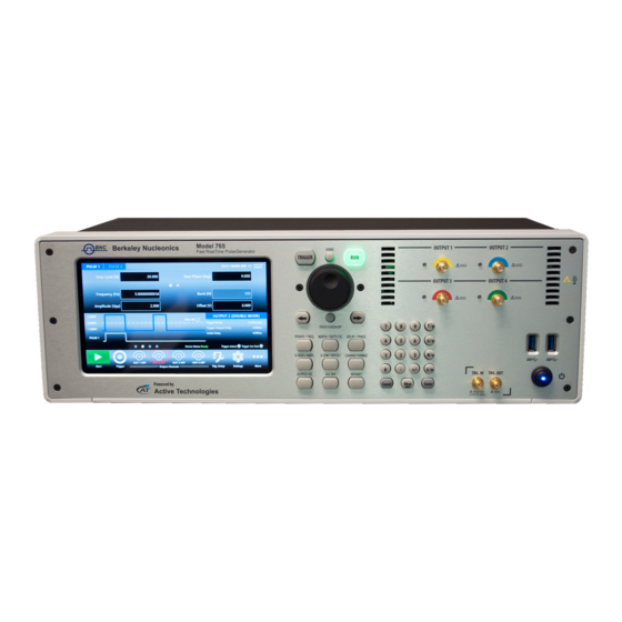
Model 765 User Manual Model 765 User Manual Instrument Overview Front Panel The numbered callouts on this image correspond with the following descriptions. 1. Single Ended USB 3.0 ports Outputs 2.Trigger IN / Trigger OUT Numeric 7” Capacitive Soft Keyboard and Keypad Touch Screen Rotary Knob... -
Page 26: Rear Panel
Model 765 User Manual them in the SimpleRider UI as positive and negative pulses. 2. TRIGGER INPUT/OUTPUT TRG.IN - SMA input connector for Trigger IN. The Trigger In input has a programmable impedance of 50 Ohm or 1k Ohm and a programmable threshold level in the range -10V to 10V. -
Page 27: Getting Started With Model 765
Model 765 User Manual 1. EXT. CLK IN Port - SMA Input for External Clock IN. The Model 765 can use an external clock source to generate the instrument time base. This feature allows to synchronize the generator with an external clock. EXT. -
Page 28: Front Panel Buttons
Model 765 User Manual Front Panel Buttons Most of the buttons you use with Model 765 are virtual ones on the touchscreen, but a few physical buttons control basic functions, such as setting the pulse amplitude, offset, delay, width etc. A physical numeric keypad is available on the front-panel and it can be used instead of the virtual numeric pad. - Page 29 Model 765 User Manual Rotary Knob Rotary Push Button Digit Selection Arrows Function Button Name If you are in a software sub-menu page, use this HOME button to return to the main page. Use this button to send an internal trigger to the TRIGGER instrument.
-
Page 30: Front Panel Numeric Keypad
Model 765 User Manual Use this button to set the period or the frequency of PERIOD/FREQ the pulse waveform. Use this button to set the width or the duty cycle of WIDTH / DUTY the pulse waveform. CYC. Use this button to set the delay or the phase of the DELAY/PHASE pulse waveform. - Page 31 Model 765 User Manual When you select a parameter on the user interface, if you press the unit measure button it will automatically set the available range linked to the parameter. Unit Measure Range Button Unit Measure Range Tera / pico Giga / nano Mega / micro Kilo / milli...
-
Page 32: Output And Pulse Definition
Model 765 User Manual Output and Pulse Definition The term Output Channel as used in this user manual, refers to the analog signal at the SMA output connectors (labels OUTPUT 1, OUTPUT 2, OUTPUT 3, OUTPUT4) on the front panel. The Output Channel parameters are: •... -
Page 33: Output Channel Parameters
Model 765 User Manual • Period [s] / Frequency [Hz] The term Pulse refers to the logical pulse that it is internally generated by the digital core of the Model 765 instrument and that it is used to compose the analog Output channel signal. Pulse Parameters Output... -
Page 34: Period / Frequency
Model 765 User Manual The output signal levels indicated by the SimpleRider UI will be delivered into 50 Ohm load. Pressing the Change Format front panel or touch button will change the display of those parameters to Amplitude[V] and Offset[V]. Amplitude[Vpp] is the difference between the active and the quiescent levels of the Output pulse. -
Page 35: Pulse Parameters
Model 765 User Manual Pulse Parameters Width / Duty Cycle The time duration of the Pulse is controlled by the Width / Duty Cycle parameter. The Width[s] defines the time interval during the Pulse N is in the active state. Pressing the Change Format button, the mode of control over the duration of the Pulse N will change to Duty Cycle. - Page 36 Model 765 User Manual In the figure below the Output 1 channel works in Double Pulse mode, it means that the Output signals is created by the logical OR combination of Pulse1/Output1 and Pulse2/Output1. If you press the Change Format button, the displayed name for the Delay parameter will change to Phase.
-
Page 37: Parameter Conflicts
Model 765 User Manual This phase angle is maintained as Period is varied. When Phase has been set, the Pulse Delay = (Phase / 360)*Period. Parameter Conflicts The following conditions must be true in order to avoid conflicts: 1. Voltage High > Voltage Low 2. - Page 38 Model 765 User Manual In Double Pulse Mode, the Output signal will be the logical OR combination of the PULSE1 and PULSE2. Berkeley Nucleonics Corporation info@berkeleynucleonics.com | www.berkeleynucleonics.com Ver. 2.3 2955 Kerner Blvd, San Rafael, CA 94901 | 800-234-7858 38 of 77...
- Page 39 Model 765 User Manual In Triple Pulse Mode, the Output signal will be the logical OR combination of the PULSE1, PULSE2 and PULSE3. In Quadruple Pulse Mode, the Output signal will be the logical OR combination of the PULSE1, PULSE2, PULSE3 and PULSE4. Berkeley Nucleonics Corporation info@berkeleynucleonics.com | www.berkeleynucleonics.com Ver.
-
Page 40: Hint: How To Generate A Clock
Model 765 User Manual Hint: how to generate a clock It is possible to create a clock with a frequency greater than 200 MHz using the multiple pulse mode through the following steps: Calculate the clock Period. PeriodClock = 1/Frequency •... - Page 41 Model 765 User Manual 2. N=2 → 2*3.003ns > 8 ns ? No. 3. N=3 → 3*3.003ns > 8 ns? Yes. The pulse mode will be Triple Pulse Mode. 4. Select Single Mode, Width = PeriodClock/2 = 1.501 ns, Delay = 0ns, Period = N*PeriodClock=9.009 ns.
-
Page 42: Trigger Controls
Model 765 User Manual Trigger Controls The Model 765 Outputs are driven from a common timebase and the channel outputs are referenced to the same trigger. It means that the output channels will share the same trigger modes but they can have different period, width and delay. Trigger Output The signal available at the Rider Pulse TRG.OUT connector is selectable positive-going or negative- going pulse, synchronized with the TRG.IN signal and the Model 765 internal timebase in Single,... -
Page 43: Trigger Modes
Model 765 User Manual Trigger Modes The Model 765 has four trigger operating characteristics: Single, Burst, Gated and Continuous. Single Mode In Single Mode the Trigger IN source can be sent externally using the TRG.IN connector or internally using the front panel button, SCPI command and timer. The Trigger Output signal is linked to one of the available Outputs using the Trigger Output →... - Page 44 Model 765 User Manual The Trigger Output width is fixed and its duration is about 10 ns. Burst Mode Burst mode is similar to Single mode, but a programmed number of Output Pulses is generated for each trigger signal that it is detected on the selected output, rather than just once. The Trigger Output signal is linked to one of the available Outputs using the Trigger Output →...
- Page 45 Model 765 User Manual This number can be programmed from 1 to 4294967295 by selecting the Burst[N] parameter on the user interface. The trigger source can be sent externally using the TRG.IN connector or internally using the front panel button, SCPI command and timer. The Trigger IN signals starts the Model 765 timebase and one TRG.OUT signal follows each trigger that is detected on the selected output channel with a delay below 100ns.
- Page 46 Model 765 User Manual Gated Mode In Gated mode, the Output Pulses of the programmed Width occur at the rate specified by Period as long as the Trigger signal is true. The trigger source can be sent externally using the TRG.IN connector or internally using the front panel button, SCPI command and timer.
- Page 47 Model 765 User Manual The width of the Trigger Output will be equal to the width of the Trigger IN signal. In Gated mode the Output pulses start after the Delay parameter plus a fixed offset below 100 ns and continue to run at the rate defined by Period, for the duration of the true state of the Trigger signal.
- Page 48 Model 765 User Manual IMPORTANT NOTE: if the selected output channel for Continuous mode will be disabled (OFF state), the TRG.OUT signal state will be ‘0’ or ‘1’ depending on the selected polarity. The width of the Trigger Output will be equal to the Period of the selected output divided by 2. Trigger Output Width = Period / 2 of the selected output.
- Page 49 Model 765 User Manual Berkeley Nucleonics Corporation info@berkeleynucleonics.com | www.berkeleynucleonics.com Ver. 2.3 2955 Kerner Blvd, San Rafael, CA 94901 | 800-234-7858 49 of 77...
- Page 50 Model 765 User Manual External Width Mode In External Width mode, the TRG.IN signal (SMA connector) is redirected to the Output channel with programmable voltage level, threshold and output impedance. NOTE: the TRG.OUT signal in Single, Burst and Gated mode will follow the output channels where the External Width Mode is not selected;...
-
Page 51: Multiple Pulse Interactions
Model 765 User Manual Multiple Pulse Interactions Here below is described the interaction of multiple pulses with various Trigger Modes. Continuous Mode Depending on the multiple pulse selection, two, three or four Pulses follow each Trigger Output rather than one. Single Mode Same as Continuous mode for the exception that the group of pulses are generated only once. - Page 52 Model 765 User Manual Burst Mode In this case the Burst N parameter specifies the number of Output Pulse groups (two, three or four) per trigger, rather than the number of Output Pulses. As example in case of Double Pulse, the first pulse of the first pair in any burst will follow the leading edge of the trigger Output by Delay 1 + Initial Delay Out.1, the second pulse in any pair follows the first by Delay parameter, and the first pulse of any pair follows the first pulse of the previous pair by the Period parameter.
-
Page 53: Quick Start
Model 765 User Manual Quick Start Single Pulse If you are a beginner user, you can follow the steps here below to generate your first pulse signal. 1. Connect the power cord and the push the front-panel on/off switch to turn on the instrument. -
Page 54: Double Pulse
Model 765 User Manual Press the OUT1 button to enable it, press OUT2 to select OUTPUT2 channel, press it again to enable it. 6. Press the Start button 7. Observe the pulse waveform displayed on the oscilloscope screen. 8. Press again the Settings button to close the Settings page. 9. - Page 55 Model 765 User Manual 4. Select “Trigger Settings” in the dropdown menu to open the Trigger Setup page and select Single as Trigger Mode, Button Only as Trigger Source. 5. Press the Start button 6. Set a Single acquisition on the oscilloscope, set the scope trigger and press the Trigger button .
- Page 56 Model 765 User Manual pulses displayed on the scope. 7. Press again the Settings button to close the Settings page. 8. Touch the Output 1 → Pulse 1 Delay parameter to change the Pulse 1 delay. You can also select the Amplitude, Period or Width parameter using the display touch screen or the front panel physical buttons.
-
Page 57: Model 765 Software
Model 765 User Manual Simple Rider PG Software User Interface Description The SimpleRider software environment provides an easy access to all product functions and parameters. Parameters Area Graph Area Command It consists of three main elements: Bar Area The Pulse and Output channel parameters area ▪... - Page 58 Model 765 User Manual If Multiple Pulse feature is Off, you can use the Swipe left or right gesture to change the Output channel selection. Berkeley Nucleonics Corporation info@berkeleynucleonics.com | www.berkeleynucleonics.com Ver. 2.3 2955 Kerner Blvd, San Rafael, CA 94901 | 800-234-7858 58 of 77...
-
Page 59: Parameters Area
Model 765 User Manual If the Multiple Pulses feature is On, you can swipe left or right on the upper part of the screen to change the selection of the Pulse and swipe left or right in the lower part of the screen to change the Output selection. - Page 60 Model 765 User Manual Touch the MIN. and MAX. buttons to display the minimum and maximum allowed value for the selected parameter; use the DEF. button to set the default value. 3. After the sign and numeric portion of the desired value have been punched in, entry with the appropriate multiplier is terminated by pressing one of the unit measure keys that are available for the current parameter.
-
Page 61: Graph Area
Model 765 User Manual Notes In Single Mode the Period and Burst parameters are not available. • In Gated and Continuous modes, the Burst parameter is not available. • Graph Area The graph area displays the Output channel and/or the Pulse waveforms with a vertical legend containing the voltage high, low level and offset. -
Page 62: Command Bar Area
Model 765 User Manual Command Bar Area The command bar contains several touch buttons to control the instrument, the following table describes them in detail. START/STOP button - Use this button to set the instrument in Running state or Ready (Stopped state). - Page 63 Model 765 User Manual Trigger Button – Use this button to send an internal software trigger to the instrument. If the instrument is armed and the trigger source is Internal, as soon as the Model 765 receive the software trigger, the output pulses will be generated.
- Page 64 Model 765 User Manual Change Format – Use this button to change the format of the output and pulse parameter (four-channel version only). Remote Button – Use this button to entry or exit from Remote Mode(four-channel version only). Calibration Button – Use this button to perform the calibration and diagnostic.
-
Page 65: Configurations
Model 765 User Manual Configurations A configuration contains the data in proprietary format relative to the current instrument settings. You can save and load the instrument settings by using the “Save As..” and “Load From…” buttons. Save As... A configuration can be saved by means of the “Save As”... -
Page 66: Load From
Model 765 User Manual Load From… Touching the “Load From” button in the “More” menu, a page will be opened that shows the list of all the saved and imported configurations. If you select an existing Configuration, you will load all the settings into the instrument. In the “Load From”... -
Page 67: Settings
Model 765 User Manual Settings The “Settings button” allows you to have access to the Output, Trigger and Clock Settings pages. Trigger Setup Press this button and select “Trigger Settings” on the dropdown list to open the Trigger Setup page where you can select the Trigger Mode, the Trigger Source, the Trigger Output Amplitude and Delay, the Trigger Input and the Timer characteristics. - Page 68 Model 765 User Manual Model 765 User Manual • Button: the instrument can receive the trigger from the software (UI button or SCPI commands) or from the front panel button only. Trigger Info The following indicators display the Trigger Input Frequency, if the trigger has been missed or if the trigger is too fast.
-
Page 69: Output Settings
Model 765 User Manual Trigger Input In Single, Burst and Gated mode, you can set the Trigger Input Threshold, the slope (positive or negative) and the input impedance (50 Ohm or 1 k Ohm). Pressing the button “Autosense”, the instrument can automatically measure the threshold of the signal applied to the Trigger In port. - Page 70 Model 765 User Manual Control Description Pulse Mode It selects the pulse mode, the pulse mode can be single, double, triple and quadruple. If you need to obtain the maximum repetition rate (800 MHz), you should select the Quadruple mode, period 5 ns and select a width of 0.625 ns on each pulse, set Delay 0ns on Pulse 1, Delay 1.25 ns on Pulse2, Delay 2.5ns on Pulse 3 and Delay 3.75ns on Pulse 4.
- Page 71 Model 765 User Manual If it is “On”, the instrument can record all the trigger events that arrive during the Initial Delay for a maximum of 2.5 µs. In this way the trigger events that occur during the Initial Delay can be detected.
- Page 72 Model 765 User Manual PRESCALER [N] TRG IN PRESCALER N=1 PRESCALER N=2 PRESCALER N=3 If you press the Left arrow on the right of the screen or you change the output pulse mode, the pulse mode flyout panel will be opened. This flyout panel explains graphically how the pulses are combined together to generate the output signal and the timing relationship between the Trigger Output, the Pulses and the selected output.
-
Page 73: Clock Settings
Model 765 User Manual Clock Settings Press this button , select “Clock Settings” on the dropdown menu to open the Clock Setup page. Clock Source: specifies the clock source as Internal or External. If Internal Clock is selected, the instrument time base is synthesized using a reference clock generated internally. -
Page 74: Remote / Locale Mode
Model 765 User Manual Remote / Locale Mode The Remote/Local page allows you to enable or disable the VXI11 server. By default the VXI11 server is enabled and it means that the instrument can accept the SCPI commands that arrive from a remote machine. -
Page 75: Remote Desktop Connection
Model 765 User Manual Remote Desktop Connection If you need to connect to the instrument using the remote desktop connection, you should insert the following credentials: Computer Name: AT User Name: AT Password: 1234 Self Calibration and Diagnostic The instrument performs a limited set of hardware tests at power-on. You can also perform the Self Calibration and Self Diagnostic from the More –>... -
Page 76: Self Calibration
Model 765 User Manual Self Calibration This calibration primarily checks DC accuracy using the internal calibration routines. 1. Click the More → Calibration and Diagnostic button 2. Click the Warm up Timer, and one dialog will pop up to show warm up timer. Wait for 30 minutes. -
Page 77: Quick Tips
Model 765 User Manual NOTE. Before executing this operation, allow a 30 minute warm-up period after powering on the instrument, because the calibration is not valid if the instrument does not reach to a valid temperature. 1. Click the More → Calibration and Diagnostic button 2.
Need help?
Do you have a question about the 765 Series and is the answer not in the manual?
Questions and answers