Table of Contents
Advertisement
Quick Links
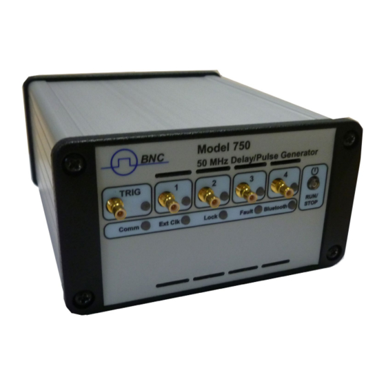
MINI PULSE & DELAY GENERATOR
Delay channel: Model 750 has 4 / 8 channels
•
100 ps delay resolution
100 second delay range
50 MHz internal trigger rate / 40 MHz external trigger rate
Channel output pulse
•
Up to 5 V, 1 ns into 50 Ω
Independent control of delay, width, polarity, burst count, and amplitude
Trigger for every channel may be single or repetitive from these sources:
•
Two inputs with pre-trigger
Or three synchronous programmable timers (0.01 Hz to 50 MHz)
Or program command
External clocking 10 MHz to 240 MHz (User programmable)
•
Controlled via Internet, Ethernet and USB
•
BNC
User Manual
Model 750
Key features
June 2021
- 1 / 42
Page
Advertisement
Table of Contents

Related Manuals for BNC 750


Summary of Contents for BNC 750
- Page 1 June 2021 Model 750 MINI PULSE & DELAY GENERATOR Key features Delay channel: Model 750 has 4 / 8 channels • 100 ps delay resolution 100 second delay range 50 MHz internal trigger rate / 40 MHz external trigger rate Channel output pulse •...
-
Page 2: Table Of Contents
User Manual – Model 750 June 2021 CONTENTS GENERAL INFORMATION............................ 3 Presentation ................................. 3 Instrument Options: .............................. 3 Installation ................................4 Operating temperature ............................4 Power On & Self-test ............................4 Applications ................................5 Accessories ................................5 SPECIFICATIONS ..............................6 OPERATING INFORMATION .......................... -
Page 3: General Information
The Mini Pulse & Delay Generator provides up to 8 independent delayed pulses at up to 50 MHz. The model Model 750 is available in 4 channels (base version) or 8 channels as an option. The form factor is a mini box. -
Page 4: Installation
To avoid any damage of the device, do not apply any voltage to either the shield or the outputs. Power cord The Model 750 comes with a removable power cord for European or US usage. It has a three- contact plug for connection to both the power source and protective ground. Operating temperature The Model 750 can be operated where the ambient air temperature is 10°C to 35°C and... -
Page 5: Applications
Instrument Triggering Components Test Application example: The Model 750 is well suited to synchronize all the devices of a Picosecond Laser system with only one compact unit and one GUI. In this application the “Clock reference input” of the pulse and delay generator receives a signal (80 MHz for example) from the laser oscillator via an O/E (optical-to-electrical converter). -
Page 6: Specifications
User Manual – Model 750 June 2021 PECIFICATIONS Delay channels Number 4 independent (up to 8 channel option) Range 100 seconds Resolution 100 ps RMS jitter < 50 ps + delay x 10 , channel to channel < 1 ns , external trigger to any channel Accuracy <... -
Page 7: Operating Information
User Manual – Model 750 June 2021 PERATING NFORMATION Operating Principles Block diagram of the generator Time CLK IN CLK OUT Base GATE/TRIGGER Channel 4 Delay Channels Outputs Trigger Time TRIGGER INPUT Controller Base 4 Delay Channels Channel Time (optional) - Page 8 User Manual – Model 750 June 2021 Channel T1 n°1) (Repetitive from Timer Channel T2 n°2) (Repetitive from Timer Channel T3 (Single from Command Channel T4 (Repetitive from Timer n°3) Mode burst and Mux Channel T1 n°1) (Repetitive from Timer Channel T2 n°1...
- Page 9 User Manual – Model 750 June 2021 External clock (80 MHz for example Channel T1 (From timer n°1 & delay = 0 Delay Delay Delay Delay Channel T2 (From timer n°1 & delay Channel T3 (From timer n°3 Channel T4 = Pulse picking...
-
Page 10: Output Pulse Into 50 Ω Or High Impedance Example
User Manual – Model 750 June 2021 Output pulse into 50 Ω or high impedance example (1 V/div, 20 ns/div) = 677 ps = 739 ps rise fall Output pulse into 50 Ω load (2 V/div, 20 ns/div) = 1.73 ns = 1.91 ns) -
Page 11: Delay Jitter & Accuracy Notes
User Manual – Model 750 June 2021 Delay Jitter & Accuracy Notes Jitter is the delay uncertainty of the channel output edge between successive triggers. The jitter specification is valid for an observation period up to 10 seconds. Jitter is measured in RMS picoseconds (ps). -
Page 12: Maximum Rate And Width Versus Model 4C Or 8C
User Manual – Model 750 June 2021 Maximum rate and width versus Model 4C or 8C Because the power consumption per bank of two channels (T1-T2 or T3-T4 or …) is limited, there are some limitations on trigger rate and pulse width. -
Page 13: Automatic Monitoring Of Operating Limits
User Manual – Model 750 June 2021 Automatic monitoring of operating limits Maximum allowed consumption, internal temperature, and minimum power supply level of the unit are permanently controlled by the embedded software. All three values are displayed in the lower part of the graphical interface. -
Page 14: Front And Rear Panel Overview
USB link Indicates that a USB connection is established • Ext DC Indicates that the Model 750 is powered by the +5 • V / DC input Notes: A standard USB connector provides power to the unit as well as communication. - Page 15 User Manual – Model 750 June 2021 Model 750 FRONT & REAR panel Front panel Rear panel - 15 / 42 Page...
- Page 16 User Manual – Model 750 June 2021 Connectors, switch Front panel Rear panel Connector Connector • • Trigger input: SMB connector Gate input: SMB connector T1 channel output: SMB connector Clock input: SMB connector T2 channel output: SMB connector Clock output: SMB connector...
-
Page 17: Gpio Interface
User Manual – Model 750 June 2021 GPIO interface Four “GPIO” lines under software command are available on the rear panel. Each line can be set as an input or an output (see command in § 4) Specifications Parameter Value... -
Page 18: Ip Address And Default Value
• EASY control and operating example Initial setup After connecting a cable from the Model 750 Ethernet port to your computer • network turn on the Model 750 with the front panel power switch. Change your laptop IP address (192.168.0.100) and Netmask (255.0.0.0). -
Page 19: Remote Control
After connecting a cable from the Model 750 Ethernet port to your computer network, enter the Model 750 IP address into your PC's browser (the IP address can be identified in § IP address). The browser will automatically open the control panel web page on your... - Page 20 User Manual – Model 750 June 2021 Setup of main menu (Model 8C) Extended Setup General remote way via Ethernet or USB and software application (see programming examples). - 20 / 42 Page...
-
Page 21: Auto Run & Auto Power
If for specific applications (system, OEM…), you want the generator to automatically power on at Power up, an “Auto Power On” function is available. To enable this function, you must contact BNC. ►Note: in Auto POWER, the RUN/STOP button is inhibited. -
Page 22: Programming The Generator
Flow control: None Opening an USB port under Windows 10 1. Open the Device Manager: 2. Connect the Model 750 to the PC with the USB cord. 3. Note the two new COM Ports that appear: - 22 / 42... - Page 23 User Manual – Model 750 June 2021 4. Open a Session under Putty (free SSH and telnet client for Windows, you can download at www.putty.org), select “Serial” in Connection Type, set Speed at 9600, and choose the second COM port that appears (COM7 in this example): 5.
- Page 24 7. Click on “Session” in the Category Tab and save the session under a name of your choice (Model 750 in this example) to retrieve it for a later connection. 8. Click the “Open” button, to open the terminal window.
- Page 25 User Manual – Model 750 June 2021 9. Now you can type any low-level command, like ‘*idn?’ followed by the “Return” key, to program or to get a response from the Model 750, as in the following example: - 25 / 42...
-
Page 26: Ethernet Connection/Communication
• new start of the device) If the IP address of the Model 750 is lost or at an unknown value, it is possible to return to the default address (192.168.0.10) with the following procedure: During the start-up phase of the Model 750, press the internal reset button on •... -
Page 27: Command Structure (Ethernet And Usb Connection)
User Manual – Model 750 June 2021 Command structure (Ethernet and USB connection) Each command description is composed of at least some of the following items (all commands are used in a telnet prompt): Full command syntax, • Form Set / Query, •... - Page 28 CLOCK:EXTERNAL:ENABLE Syntax: CLOCK:EXTERNAL:ENABLE <boolean> CLOCK:EXTERNAL:ENABLE? Form: Set & Query Description: Set the Model 750 in external or internal clock mode. Parameter: boolean: YES or NO RST value Set the Model 750 in external clock mode Example: CLOCK:EXTERNAL:ENABLE YES CLOCK:EXTERNAL:ENABLE? => :CLOCK:EXTERNAL:ENABLE YES...
- Page 29 User Manual – Model 750 June 2021 CLOCK:OUTPUT:ENABLE Syntax: CLOCK:OUTPUT:ENABLE <boolean> CLOCK:OUTPUT:ENABLE? Form: Set & Query Description: Activate or inhibit the clock output. Parameter: boolean: YES or NO RST value Example: Activate the clock output CLOCK:OUTPUT:ENABLE YES CLOCK:OUTPUT:ENABLE? => :CLOCK:OUTPUT:ENABLE YES...
- Page 30 Example: TRIGGER:EXEC Syntax: RUN <boolean> Form: Set & Query Description: Set the Model 750 in RUN or STOP state. Parameter: ON or OFF RST value Example: Set the Model 750 in RUN state RUN ON RUN? => :RUN ON...
- Page 31 User Manual – Model 750 June 2021 CHANNEL:SOURCE Syntax: CHANNEL:SOURCE x,OFF|F1|F2|F3|EXT1|EXT2|MANUAL CHANNEL:SOURCE? x Form: Set & Query Description: Set the channel trigger source. Parameter: x: 1 to 4, n° of the channel OFF for inhibition F1 for internal frequency generator n° 1 F2 for internal frequency generator n°...
- Page 32 User Manual – Model 750 June 2021 CHANNEL:WIDTH Syntax: CHANNEL:WIDTH x,<width> CHANNEL:WIDTH? x Form: Set & Query Description: Set the channel output width. Parameter: x: 1 to 4, n° of the channel width: output width in ns, from 10 ns to 10 s...
- Page 33 User Manual – Model 750 June 2021 CHANNEL:GATED Syntax: CHANNEL:GATED x,<boolean> CHANNEL:GATED? x Form: Set & Query Description: Activate or inhibit the External Gate Input for a channel. Parameter: x: 1 to 4, n° of the channel boolean: YES or NO...
- Page 34 User Manual – Model 750 June 2021 GPIO GPIO:CHANNEL:DIRECTION Syntax: GPIO:CHANNEL:DIRECTION x,INPUT|OUTPUT GPIO:CHANNEL:DIRECTION? x Form: Set & Query Description: Set the GPIO direction. Parameter: x: 1 to 4, n° of the GPIO INPUT: the GPIO in an input OUTPUT: the GPIO in an output...
- Page 35 User Manual – Model 750 June 2021 Status STAT? TEMP Syntax: STAT? TEMP Form: Query Description: Returns the internal temperature, in °C. Parameter: RST value Example: STAT? TEMP => :STAT TEMP,39.8 STAT? POW Syntax: STAT? POW Form: Query Description: Returns the values of the internal voltage in V, the supply current in A, and the source of the supply (INT or EXT).
- Page 36 User Manual – Model 750 June 2021 STAT CLEAR Syntax: STAT CLEAR Form: Description: Clears the alarms Parameter: RST value Example: STAT ALARM => :STAT ALARM,0,0,0,1 Current alarm is active STAT CLEAR Clears the current alarm (if the cause has been fixed) STAT ALARM =>...
- Page 37 User Manual – Model 750 June 2021 Network Timeout Syntax: NETWORK:TCP:TIMEOUT <timeout in seconds> Form: Set & Query Description: Set network Timeout after a period of inactivity Parameter: Timeout in seconds: time after which the network disconnects in the event of non-activity (if set to 0, there is no timeout)
-
Page 38: Device Programming Examples
User Manual – Model 750 June 2021 Device programming examples Example N°1: Use the following commands to provide a repetitive pulse on T1 output. Pulse width = 10 µs, pulse amplitude = 4.5 V, Rate = 1 Hz CLOCK:INTERNAL:FREQUENCY 1,1.0<cr><lf>... - Page 39 User Manual – Model 750 June 2021 Example N°3: Use the following commands to combine T1 output with T2 output. T1 output; Pulse width = 10 µs, pulse amplitude = 4.5 V, Rate = 10 kHz T2 output; Pulse width = 20 µs, pulse amplitude = 4.5 V, Rate = 10 kHz CHANNEL:DELAY 1,0<cr><lf>...
- Page 40 User Manual – Model 750 June 2021 Example N°4: Use the following commands to provide a burst on T1 and combine T1 output with T2 output. CHANNEL:DELAY 1,0<cr><lf> Set channel 1 delay to 0 ps CHANNEL:WIDTH 1,10000<cr><lf> Set channel 1 width to 10 µs CHANNEL:DELAY 2,40000000<cr><lf>...
-
Page 41: Index: Ethernet/Usb Command
User Manual – Model 750 June 2021 INDEX: E /USB THERNET COMMAND *IDN? ..........27 RUN ..........21 CHANNEL AMPLITUDE ........31 BURST NETWORK COUNT .........32 GWADDRESS.........36 DELAY ..........30 IPADDRESS ........36 GATED .........33 MACADDRESS .......37 MUX ..........33 NETMASK ........36 PERIOD ........32 POLARITY ........32 TIMEOUT ........37... - Page 42 User Manual – Model 750 June 2021 - 42 / 42 Page...
Need help?
Do you have a question about the 750 and is the answer not in the manual?
Questions and answers