Table of Contents
Advertisement
Quick Links
OIL FIRED FURNACE
DOWNFLOW / HORIZONTAL
INSTALLER / SERVICE TECHNICIAN:
USE THE INFORMATION IN THIS MANUAL FOR THE INSTALLATION AND
SERVICING OF THE FURNACE AND KEEP THE DOCUMENT NEAR THE UNIT
FOR FUTURE REFERENCE.
HOMEOWNER:
PLEASE KEEP THIS MANUAL NEAR THE FURNACE FOR FUTURE
REFERENCE.
Printed in Canada
Printed on 100% recycled paper
Models:
ODH53-F
Caution: Do not tamper with the
unit or its controls. Call a
qualified service technician.
Manufactured by:
Dettson Industries Inc.
Sherbrooke, Québec - Canada
www.dettson.ca
2015-08-11
X40084 Rev. M
Advertisement
Table of Contents

Subscribe to Our Youtube Channel
Related Manuals for Dettson ODH53-F


Summary of Contents for Dettson ODH53-F
- Page 1 USE THE INFORMATION IN THIS MANUAL FOR THE INSTALLATION AND qualified service technician. SERVICING OF THE FURNACE AND KEEP THE DOCUMENT NEAR THE UNIT FOR FUTURE REFERENCE. Manufactured by: Dettson Industries Inc. HOMEOWNER: Sherbrooke, Québec - Canada PLEASE KEEP THIS MANUAL NEAR THE FURNACE FOR FUTURE REFERENCE.
-
Page 2: Table Of Contents
Figure 4: Limit control ..............12 F - Chimney venting ..............10 Figure 5: Furnace Dimensions ............17 Figure 6: Electrical Diagram, ODH53-F ......... 18 3.2.4- Sequence of operation Side Wall Venting system ..10 Figure 7: Parts List – Exploded view ..........19 3.3-... -
Page 3: 1- Safety
1- SAFETY NOTE: It is the personal responsibility and obligation of the customer to contact a qualified installer to ensure that the installation conforms to governing local and/or 1.1- DANGER, WARNING AND CAUTION national codes and ordinances. The words DANGER, WARNING and CAUTION are used to This furnace is NOT approved for installation in mobile homes, identify the levels of seriousness of certain hazards. -
Page 4: Freezing Temperatures And Your Structure
1.5- INSTALLATION REGULATIONS CAUTION Ensure that the area around the combustion air intake terminal is free of snow, ice and debris. All local and national code requirements governing the installation of oil burning equipment, wiring and flue connections MUST be followed. CAUTION Some of the codes that may be applicable are: An air pressure switch MUST be used when the furnace... -
Page 5: 2- Installation
maximum efficiency and without the use of a side-wall power vent. 2- INSTALLATION The unit will operate at a positive over fire draft and flue draft. 2.1- LOCATION OF THE FURNACE WARNING CAUTION Poisonous carbon monoxide gas hazard. Carefully check your furnace upon delivery for any Never vent this furnace together with another evidence of damage that may have occurred during combustion appliance when side-wall venting. -
Page 6: 3- Side-Wall Venting
Applying Table 2 The following table is an excerpt from the Installation Code and indicates the permitted flue sizes and minimum base temperatures for circular flues in chimneys with thermal resistance of less than R6 (6 If a furnace with a 0.60 USGPH nozzle is to be connected to a 20 foot hr F / Btu). -
Page 7: 3- Ducted Outdoor Combustion Air
2.3.3- Ducted outdoor combustion air 2.4.1- BURNER INSTALLATION Mounting the burner Three burners are set up to duct outside combustion air directly to the burner: the Beckett AFII and Riello 40-BF for side-wall venting, and the The warm air furnace burner mounting plate has a 4-bolt Beckett AFG for use with conventional chimney venting. -
Page 8: Blocked Vent Shut-Off (Bvso) For Chimney Venting
Checking the air and turbulator settings 2.6- INSTALLING ACCESSORIES Before starting the burner for the first time, adjust the air and turbulator WARNING settings to those listed in Table 4. Once the burner becomes operational, final adjustments will be necessary. Checking the fuel supply system Electrical shock hazard. - Page 9 CAUTION Dampers (purchased locally) MUST be automatic. WARNING Poisonous carbon monoxide gas hazard. Do NOT draw return air from inside a closet or utility room. Return air duct MUST be sealed to furnace casing. Failure to properly seal duct can result in death, personal injury and/or property damage.
-
Page 10: 3- Operation
After the pre-purge period, the solenoid valve opens, allowing oil to 3- OPERATION flow through the nozzle. At the same time, the burner motor ignition coil produces spark; 3.1- MANUAL OPERATION SWITCHES The ignition transformer spark ignites the oil spray; Cad cell senses flame and burner continues to fire. -
Page 11: Checks And Adjustments
then the thermostat circuit is opened and the burner will go into a 3.3.3- Combustion chamber curing 15 seconds post-purge and then shut down; Once the burner blower shuts down, after the post-purge, the Some moisture and binders remain in the ceramic combustion chamber pressure switch contacts will re-close. -
Page 12: 8- Fan-Limit Adjustment
3.3.10- Side Wall Venting Blocked intake / blocked vent Figure 3: Sight glass test On side-wall vented furnaces, the Side Wall venting system incorporates a safety shutdown system that will shut the burner down before #1 smoke occurs due to the presence of a blocked intake or blocked vent outlet. -
Page 13: 4- Maintenance
Soot will have collected in the first sections of the heat exchangers only 4- MAINTENANCE if the burner was started after the combustion chamber was flooded with fuel oil, or if the burner has been operating in a severely contaminated condition. -
Page 14: 3- Drawer Assembly
Replacing the fire pot the VRV gate is pivoting freely and that the pivot rod is in a horizontal position. Also, check that the counterweight has been properly adjusted Align the slot at the front part of the fire pot with the burner tube in accordance with CAS-2B installation instructions. -
Page 15: 5- Technical Informations
5- TECHNICAL INFORMATIONS Model: Serial number: Installation date of the furnace: Service telephone # - Day: Night: Dealer name and address: START-UP TEST RESULTS Nozzle: Pressure: lbpsi Burner adjustments: Primary air Fine air Drawer Assembly Smoke scale: (Bacharach) Gross stack °F temperature: Ambient temperature:... -
Page 16: Table 3: Technical Specifications
Table 3: Technical specifications Model : ODH53-F RATING AND PERFORMANCE Firing rate (USGPH) 0.50 0.63 0.75 0.72 Input (BTU/h) 70 000 88 200 105 000 100 800 Heating capacity, chimney installation (BTU/h) 58 000 72 500 85 200 Heating capacity, side-wall installation (BTU/h) -
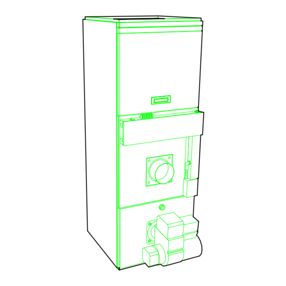
Page 17: Figure 5: Furnace Dimensions
Figure 5: Furnace Dimensions... -
Page 18: Figure 6: Electrical Diagram, Odh53-F
Figure 6: Electrical Diagram, ODH53-F... -
Page 19: Figure 7: Parts List - Exploded View
Figure 7: Parts List – Exploded view B50030 Rev. C... -
Page 20: Table 5: Parts List
Table 5: Parts list ITEM DESCRIPTION PART # B30776-01 Com plete heat exchanger B30542-01 Top heat exchanger B30517 Gas ket, heat exchanger F07O001 Hexagonal flange nut 3/8-16NC bras s B30518 Com bus tion cham ber B30757 Bottom heat exchanger F06F015 Was her 1 7/16 zinc B30507 Front filter drawer...
Need help?
Do you have a question about the ODH53-F and is the answer not in the manual?
Questions and answers