Table of Contents
Advertisement
Quick Links
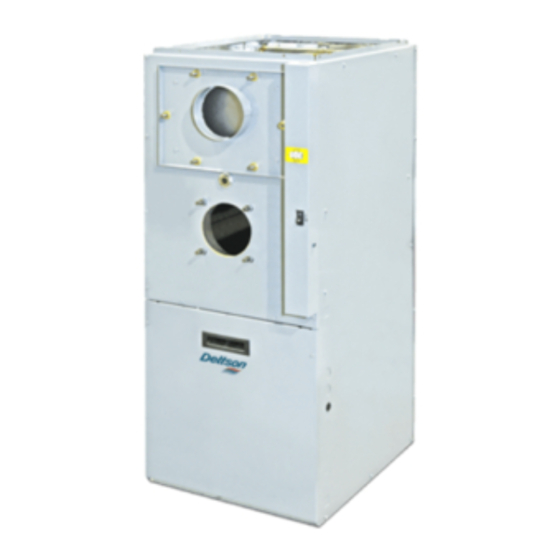
MULTIPOSITION
OIL FIRED FURNACE
INSTALLER / SERVICE TECHNICIAN:
USE THE INFORMATION IN THIS MANUAL FOR THE
INSTALLATION / SERVICING OF THE FURNACE AND KEEP
THE
DOCUMENT
REFERENCE.
HOMEOWNER:
PLEASE KEEP THIS MANUAL NEAR THE FURNACE FOR
FUTURE REFERENCE.
Printed on 100% recycled paper
DNS-1225A
NEAR
THE
UNIT
OMF154L20A
OMV154L20A
Attention:
Do not tamper with the unit or its
controls. Call a qualified service
FOR
FUTURE
technician.
Manufactured by :
Dettson Industries inc.
3400 Industrial Boulevard
Sherbrooke, Québec – Canada
J1L 1V8
2011-07-04
MODEL:
C
X40181 Rev. B
US
Advertisement
Table of Contents

Subscribe to Our Youtube Channel
Related Manuals for Dettson OMF154L20A


Summary of Contents for Dettson OMF154L20A
- Page 1 DOCUMENT NEAR UNIT FUTURE technician. REFERENCE. Manufactured by : HOMEOWNER: Dettson Industries inc. 3400 Industrial Boulevard PLEASE KEEP THIS MANUAL NEAR THE FURNACE FOR Sherbrooke, Québec – Canada FUTURE REFERENCE. J1L 1V8 Printed on 100% recycled paper 2011-07-04 X40181 Rev. B...
-
Page 2: Table Of Contents
TABLE OF CONTENTS SAFETY REGULATIONS..............................4 SAFETY LABELING AND WARNING SIGNS ......................4 IMPORTANT INFORMATION............................. 4 DETECTION SYSTEMS..............................4 DANGER OF FREEZING............................... 4 INSTALLATION ..................................5 POSITIONING THE FURNACE............................ 5 CONFIGURATIONS ............................... 5 ELECTRICAL SYSTEM..............................6 INSTALLATION OF THE THERMOSTAT......................... 6 INSTALLATION OF THE BURNER .......................... - Page 3 FIGURES Figure 1 - Location and dimensions of ventilation air openings in a closet door ....5 Figure 2 - Upflow Installation .....................5 Figure 3 - Downflow Installation ....................6 Figure 4 - Horizontal Installation....................6 Figure 5 - Thermostat wiring, heating and air conditioning with 4-speed motor ....6 Figure 6 - Thermostat wiring, heating and air conditioning with ECM variable speed motor ....................7 Figure 7 - Thermostat wiring,heating and air conditioning/heat pump with ECM...
-
Page 4: Safety Regulations
Before calling for service, be sure to have the SAFETY REGULATIONS information page of your manual close by in order to be able to provide the contractor with the required information, such as the model and SAFETY LABELING AND serial numbers of the furnace. WARNING SIGNS The words DANGER, WARNING AND CAUTION are used WARNING... -
Page 5: Installation
The unit must be installed in an area where the ambient 2 INSTALLATION and return air temperatures are above 15°C (60°F). In addition, the furnace should be installed as closely as This furnace is a true multi-position unit, in that it will possible to the vent, so that the connections are direct function in an upflow, downflow or horizontal configuration and kept to a minimum. -
Page 6: Electrical System
2.2.2 Upflow Installation ELECTRICAL SYSTEM When the furnace is installed in the downflow position on a CAUTION combustible floor, the clearances from combustibles must The exterior of the unit must have an uninterrupted adhered downflow base DFB-104 ground to minimize the risk of bodily harm, if ever an KLASB1001DET can be used to ensure these clearances. -
Page 7: 2.5 Installation Of The Burner
Position the mounting gasket between the mounting Figure 6 - Thermostat wiring, heating and air flange and the burner mounting plate. Align the holes conditioning with ECM variable speed motor in the burner mounting plate with the studs on the mounting flange and bolt securely in place. -
Page 8: Blocked Vent Shut-Off Device (Bvso) For Chimney Venting
chimney into which a solid fuel burning furnace is already WARNING being vented. Before venting this furnace into a chimney, its condition must Poisonous carbon monoxide gas hazard. be checked and repairs made, if necessary. Also, the chimney Comply with NFPA 31 (U.S.) and CSA B139 (Canada) lining and dimensions must conform to local and national standards installation... -
Page 9: Oil Tank
provided with the burner, the fresh-air supply kit or the side- 2.11 SUPPLY AIR ADJUSTMENTS wall venting kit. (4 SPEED MOTORS) OIL TANK On units equipped with 4-speed blower motors, the supply air must be adjusted based on heating/air conditioning WARNING output and the static pressure of the duct system. -
Page 10: Supply Air Adjustments (Ecm Variable Speed Motors)
2.12 SUPPLY AIR ADJUSTMENTS (ECM VARIABLE SPEED MOTORS) On units equipped with ECM variable speed blower motors, the air supply must be adjusted based on heating/air conditioning output. The start/stop delays of the blower must also be adjusted by positioning the DIP switches on the electronic board. -
Page 11: Operation
and pump. Slowly close and tighten the bleed screw. Once closed, the flame will light up. OPERATION 3.3.2 Pressure adjustment START-UP The oil pressure must be adjusted according to the Before starting up the unit, be sure to check that the following Technical Specifications of this manual. - Page 12 minutes, the draft regulator should be set to between -0.025" Press the reset button on the burner primary control and -0.060" W.C. (relay); Set the thermostat higher than room temperature; If the burner motor does not start or ignition fails, turn Overfire pressure test off the disconnect switch and CALL A QUALIFIED 3.3.5...
-
Page 13: Maintenance
CLEANING THE BLOCKED VENT MAINTENANCE SHUT-OFF DEVICE (BVSO) WARNING For continuous safe operation, the Blocked Vent Shut-off device (BVSO) must be inspected and maintained annually by a qualified service technician. Electrical shock hazard. Disconnect power to the appliance; Turn OFF power and fuel to the furnace before any Remove the two screws holding on the BVSO disassembly or servicing. -
Page 14: Furnace Information
5 FURNACE INFORMATION Model: Serial number: Furnace installation date: Service telephone #-Day: Night: Dealer name and address: START-UP RESULTS Nozzle: Pressure: lb/po Burner adjustments: Primary air Fine air Drawer Assembly Smoke scale: (Bacharach) Gross stack temperature: °F Ambient temperature: °F Chimney draft : "... -
Page 15: Table 6 - Technical Specifications
Table 6 - Technical Specifications 154 Series, m ulti-position m odels UNITS WITH 1.0 HP 4-SP. MOTOR UNITS WITH 1.0 HP ECM MOTOR RATING AND PERFORMANCE Firing rate (USGPH)* 0,90 1,10 0,90 1,10 Input (BTU/h)* 126 000 154 000 126 000 154 000 Maximum Heating capacity, (BTU/h)* 107 000... -
Page 16: Table 7 - Airflow Data Model With 1Hp Ecm Motor
Table 7 - Airflow data model with 1HP ECM motor OIL HEATING MODE 24 VAC input (R) on W only SW1- HEAT HEAT INPUT CFM with SW3-ADJ CFM with SW3-ADJ CFM with SW3-ADJ DIP switch position (USGPH) DIP switch position A DIP switch position B DIP switch position C 0,90... -
Page 17: Table 8 - Airflow Data Model With 1Hp 4-Speed Motor
Table 8 - Airflow data model with 1HP 4-speed motor EXTERNAL STATIC PRESSURE WITH AIR FILTER BLOWER SPEED 0.2" (W.C.) 0.3" (W.C.) 0.4" (W.C.) 0.5" (W.C.) 0.6" (W.C.) 0.7" (W.C.) HIGH 2130 2085 1995 1915 1820 1745 1930 1855 1800 1750 1675 1615... -
Page 18: Figure 9 - Furnace Dimensions
Figure 9 - Furnace Dimensions... -
Page 19: Figure 10 - Wiring Diagram 4-Speed Motor (Psc)
Figure 10 - Wiring diagram 4-speed motor (PSC) -
Page 20: Figure 11 - Wiring Diagram Variable Speed Motor (Ecm)
Figure 11 - Wiring diagram variable speed motor (ECM) -
Page 21: Figure 12 - Parts List With 4-Speed Motor (Psc)
Figure 12 - Parts list with 4-speed motor (PSC) B500111A... -
Page 22: Table 10 - Parts List With 4-Speed Motor (Psc)
Table 10 - Parts list with 4-speed motor (PSC) ITEM PART # DESCRIPTION COMMENTS B03820 HEAT EXCHANGER Heat exchanger only J06L002 SEAL STRIP, DIA 1/8 x 25' B03856-01 FRONT PANEL ASSEMBLY Panel, insulation and labels included B03866 FRONT PANEL INSULATION B03835-01 BAFFLE, LATERAL B03855-01... -
Page 23: Figure 13 - Parts List With Variable Speed Motor (Ecm)
Figure 13 - Parts list with variable speed motor (ECM) B50112A... -
Page 24: Table 11 - Parts List With Variable Speed Motor (Ecm)
Table 11 - Parts list with variable speed motor (ECM) ITEM PART # DESCRIPTION COMMENTS B03820 HEAT EXCHANGER Heat exchanger only J06L002 SEAL STRIP, DIA 1/8 x 25' B03856-01 FRONT PANEL ASSEMBLY Panel, insulation and labels included B03866 FRONT PANEL INSULATION B03835-01 BAFFLE, LATERAL B03855-01...
Need help?
Do you have a question about the OMF154L20A and is the answer not in the manual?
Questions and answers