
Related Manuals for FIC VA-501


Summary of Contents for FIC VA-501
- Page 1 VA-501 MAINBOARD MANUAL DOC No. : 15609 Rev. : A0 Date : 09, 1996 Part No. : 25-10601-00...
-
Page 2: Table Of Contents
Table of Contents Chapter 1 Overview Main Features ..................2 Chapter 2 Installation Procedures Mainboard Layout .................. 4 1). Set System Jumpers ................5 Flash ROM Voltage Select: EP1 and EP2 ......5 CPU to SRAM Data Write Mode Selection: SRAM1....5 Clear Password: CPW............ - Page 3 VA-501 Mainboard Manual PCI Configuration Setup................. 31 PnP Configuration Setup ................ 33 Load BIOS Defaults ................34 Load Setup Defaults................34 Supervisor/User Password..............34 IDE HDD Auto Detection............... 35 Save and Exit Setup ................36 Exit without Saving................36...
-
Page 4: Main Features
Chapter 1 Main Features The VA-501 mainboard comes with the following high-performance features: Easy Installation Award BIOS with support for Plug and Play, auto detection of Hard Drive and IDE features, MS Windows 95 and Windows NT compatible. Flexible Processor Support The onboard 321-pin ZIF socket supports Intel Pentium (P54C) CPU speed 75/90/100/120/133/150/166/180/200 MHz processors / P54CTB. - Page 5 VA-501 Mainboard Manual ISA & PCI Expansion Slots Three 16-bit ISA and four 32-bit PCI expansion slots provide all the room you need to install a full range of add-on cards. Enhanced PCI Bus Master IDE Controller Integrated Enhanced PCI local bus IDE controller with two connectors supports up to four IDE devices such as Hard Disk, CD-ROM or Tape Backup drives via two channels for high speed data throughput.
-
Page 6: Chapter 2 Installation Procedures
Chapter 2 Installation Procedures The VA-501 has several user-adjustable jumpers on the board that allow you to configure your system to suit your requirements. This chapter contains information on the various jumper settings on your mainboard. To set up your computer, you should follow these installation steps:... -
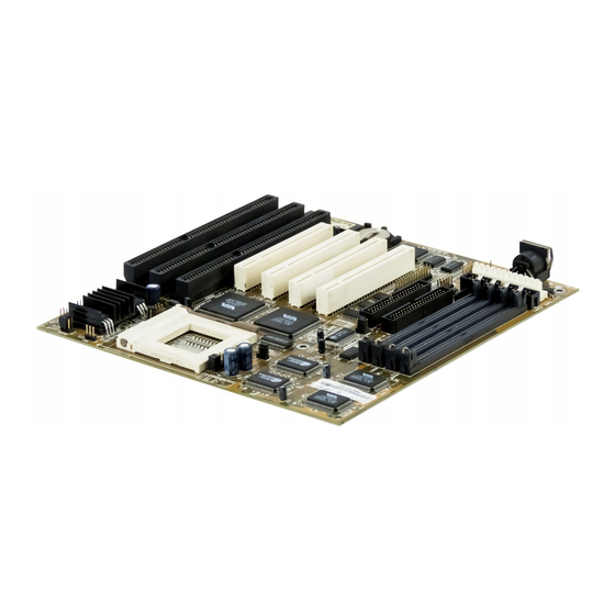
Page 7: Mainboard Layout
VA-501 Mainboard Manual Mainboard Layout... -
Page 8: Set System Jumpers
Installation Procedures 1). Set System Jumpers NOTE : Users are not encouraged to change the jumper settings not listed in this manual. Changing the jumper settings improperly may adversely affect system performance. Flash ROM Voltage Select: EP1 and EP2 These two jumpers allow you to select the different voltages of the flash ROM. CPU to SRAM Data Write Mode Selection: SRAM1 This jumper allows you to select the CPU to SRAM data read/write mode. -
Page 9: Clear Password: Cpw
VA-501 Mainboard Manual Clear Password: CPW The password clear jumper lets you set the password configuration to “Enabled” or “Disabled”. You may need to enable password clear if forget your password. PCI 2 ID: PCI2ID This setting is provided to allow you to install more than PCI add-on card released before the launch of the PCI Encoding Standard in 1993. -
Page 10: Install Dram Modules
Installation Procedures 2). Install DRAM Modules The VA-501 supports standard Fast Page Mode and Extended Data Out DRAM; accommodates onboard memory from 8 to 64MB using SIMMs. The mainboard has two memory banks - Bank 0 and Bank 1 which can use different types of SIMMs. -
Page 11: Installation Instructions
VA-501 Mainboard Manual Installation Instructions NOTE : Always observe static electricity precautions. See “Handling Precautions” at the start of this manual. 1. Locate the SIMM on the mainboard. 2. Carefully fit a SIMM at a 45 degree angle into each of the empty sockets to be populated. -
Page 12: Cache Memory
Installation Procedures Cache Memory The VA-501 provides the onboard 256KB/512KB cache SRAMs. The corresponding jumper settings are shown below. -
Page 13: Install The Cpus
VA-501 Mainboard Manual 3). Install the CPUs The VA-501 provides one onboard Zero Insertion Force (ZIF) socket for the processor. CAUTION : 1. Always turn the system power off before installing or removing any device. 2. Always observe static electricity precautions. -
Page 14: Cpu To Bus Frequency Ratio: Freq1 And Freq2
Installation Procedures CPU to Bus Frequency Ratio: FREQ1 and FREQ2 These two jumpers are used to configure the ratio of the CPU frequency to the bus clock. NOTE : * This CPU had not yet been tested when this manual was printed. -
Page 15: Cpu External Clock (Bus) Frequency: Clk1 And Clk2
VA-501 Mainboard Manual CPU External Clock (Bus) Frequency: CLK1 and CLK2 The table below shows the jumper settings for the different CPU speed configurations. NOTE : * This CPU had not yet been tested when this manual was printed. -
Page 16: Cpu Voltage Selection: Vr1 And Vr2
Installation Procedures CPU Voltage Selection: VR1 and VR2... -
Page 17: Cpu Voltage Markings
VA-501 Mainboard Manual CPU Voltage Markings... -
Page 18: Installation Of Cyrix (Or Ibm) 6X86 Cpu Fan
Installation Procedures Installation of Cyrix (or IBM) 6x86 CPU Fan CAUTION : When you install a Cyrix (or IBM) 6x86 CPU fan, please pay attention to the direction of the air flow. Make sure the air flow is in the direction of the regulator;... -
Page 19: Connect Cables And Power Supply
VA-501 Mainboard Manual 4). Connect Cables and Power Supply Serial Port Connectors: COM1 and COM2 This two 9 pin D-Sub male connectors allow you to connect with your devices that take serial ports, such as a serial mouse or a modem. Usually, the serial mouse is connected to COM1, and the modem is connected to COM2. -
Page 20: Block Connector
Installation Procedures Block Connector This block connector includes: PW_LED, KB_LOCK, TB_LED, SP_SW, SP_LED, SPK, IDE_LED, RST connectors. Item Connector Pin Type Feature PW_LED 2-pin male indicates the system power status KB_LOCK 2-pin male allows the keyboard to access the system TB_LED 2-pin male indicates the system speed is in normal or... -
Page 21: Power Connector: Power
VA-501 Mainboard Manual Power Connector: POWER This 12-pin block connector is used for connecting to your standard 5V power supply. In the figure below, notice that, in most cases, there are two marks “P8” and “P9” on the surface of the connector. You have to insert the “P8” plug into the “P8”... -
Page 22: Chapter 3 Award Bios Setup
Chapter 3 Award BIOS Setup The mainboard comes with the Award BIOS chip that contains the ROM Setup information of your system. This chip serves as an interface between the processor and the rest of the mainboard’s components. This chapter explains the information contained in the Setup program and tells you how to modify the settings according to your system configuration. -
Page 23: Standard Cmos Setup
VA-501 Mainboard Manual Standard CMOS Setup The Standard CMOS Setup screen is displayed above. System BIOS automatically detects memory size, thus no changes are necessary. It has a few items for setting. Each item may have one or more option settings. It allows... - Page 24 Award BIOS Setup PRECOMP: The cylinder number at which the disk drive changes the write timing. LANDZ: The cylinder number that the disk drive heads (read/write) are seated when the disk drive is parked. SECTOR: The sector number of each track defined on the hard disk. The range is from 1 to 64.
-
Page 25: Bios Features Setup
VA-501 Mainboard Manual BIOS Features Setup Moving around the BIOS and Chipset Features (refer to the next section) Setup programs shown works the same way as moving around the Standard CMOS Setup program. Users are not encouraged to run the BIOS and Chipset Features Setup programs. - Page 26 Award BIOS Setup Boot Sequence Allows the system BIOS to first try to boot the operating system from the selected disk drive. The options are: A, C (Default); C, A; C, CDROM, A; CDROM, C, A. Swap Floppy Drive When enabled, allows you to switch the order in which the operating system accesses the floppy drives during boot up.
- Page 27 VA-501 Mainboard Manual Security Option Allows you to set the security level of the system. The options are: Setup (Default), System. PCI/VGA Palette Snoop When enabled, allows you install an enhanced graphics adapter card. If your graphics adapter card does not support the Pallete Snoop function, please set at Disable to avoid system malfunctions.
-
Page 28: Chipset Features Setup
Award BIOS Setup Chipset Features Setup Video BIOS Cacheable When enabled, allows the system to use the video BIOS codes from SRAMs, instead of the slower DRAMs or ROMs. The options are: Enabled (Default), Disabled. System BIOS Cacheable When enabled, allows the ROM area F000H-FFFFH to be cacheable when cache controller is activated. - Page 29 VA-501 Mainboard Manual DRAM Timing Control Allows you to speed up the data access of 82C586. The options: Normal, Fast (Default), Turbo. Enhanced Page Mode When enabled, it allows the system BIOS to pre-determine the next access is on or off page. This leads the start of precharge time if off page. The options: Enabled (Default), Disabled.
- Page 30 Award BIOS Setup IDE Primary Slave PIO Allows you to select the first PCI IDE channel of the primary slave hard disk mode or to detect it by the BIOS. The options are: Auto (Default), Mode 0, Mode 1, Mode 2, Mode 3, Mode IDE Secondary Master PIO Allows you to select first PCI IDE channel of the primary master hard disk mode or to detect it by the BIOS.
- Page 31 VA-501 Mainboard Manual Onboard Parallel Mode Allows you to connect with an advanced printer I/O mode. The options are: SPP (Default), EPP, ECP, ECP/EPP.
-
Page 32: Power Management Setup
Award BIOS Setup Power Management Setup Power Management When enabled, allows you to use Power Management features. The options are: Enabled, Disabled (Default). PM Control by APM The option No allows the BIOS to ignore the APM (Advanced Power Management) specification. Selecting Yes will allow the BIOS wait for APM’s prompt before it enters Doze mode, Standby mode, or Suspend mode. - Page 33 VA-501 Mainboard Manual Video Off Method The option V/H SYNC+Blank allows the BIOS to blank off screen display by turning off the V-Sync and H-Sync signals sent from add-on VGA card. DPMS Support allows the BIOS to blank off screen display by your add-on VGA card which supports DPMS (Display Power Management Signaling function.) Blank Screen allows the BIOS to blank screen display by turning...
- Page 34 Award BIOS Setup Selecting ON will enable the power management timers when a no activity events is detected in the VGA. Selecting OFF to disable the PM timer even if a no activity event is detected. The options are: OFF (Default), ON. LPT &...
-
Page 35: Pci Configuration Setup
VA-501 Mainboard Manual PCI Configuration Setup PCI IRQ Actived By If your IDE card is triggered by edge, set it at Edge. The options are: Level (Default), Edge. PCI IDE 2nd Channel When enabled, allows you to use the second channel of PCI IDE. - Page 36 Award BIOS Setup PCI Burst When enabled, data transfer on PCI Buses will improve. Disable this item during trouble-shooting. The options are: Disabled, Enabled (Default). PCI Master 0 WS Write When enabled, allows a zero-wait-state-cycle delay when the PCI master drive writes data to DRAM.
-
Page 37: Pnp Configuration Setup
VA-501 Mainboard Manual PnP Configuration Setup Resources Controlled By If you set at Auto, the BIOS automatically arranges all system resources for you. If there are conflicts or you are not satisfy with the configuration, simply set all the resources listed in the above figure by selecting Manual. -
Page 38: Load Bios Defaults
Award BIOS Setup Load BIOS Defaults The BIOS defaults contain the most appropriate values of the system parameters that allow minimum system performance. The OEM manufacturer may change the defaults through MODBIN before the binary image burns into the ROM. Load Setup Defaults Selecting this field loads the factory defaults for BIOS and Chipset Features which the system automatically detects. -
Page 39: Ide Hdd Auto Detection
VA-501 Mainboard Manual IDE HDD Auto Detection The IDE Hard Disk Drive Auto Detection feature automatically configures your new hard disk. Use it for a quick configuration of new hard drives. This feature allows you to set the parameters of up to four IDE HDDs. The option(s) with (Y) is recommended by the system BIOS. -
Page 40: Save And Exit Setup
Award BIOS Setup Save and Exit Setup After you have made changes under Setup, press Esc to return to the main menu. Move cursor to Save and Exit Setup or press F10 and then press Y to change the CMOS Setup. If you did not change anything, press Esc again or move cursor to Exit Without Saving and press Y to retain the Setup settings.
Need help?
Do you have a question about the VA-501 and is the answer not in the manual?
Questions and answers