
Related Manuals for FIC VI35VL


Summary of Contents for FIC VI35VL
- Page 1 VI35VL MAINBOARD MANUAL DOC No.: M03101 Rev. |: A0 Date |:2, 2003 Part No. |: 25-11127-00...
- Page 2 Notice Handling Precautions Warning: 1. Static electricity may cause damage to the integrated circuits on the motherboard. Before handling any motherboard outside of its protective packaging, ensure that there is no static electric charge in your body. 2. There is a danger of explosion if the battery is incorrectly replaced.
-
Page 3: Table Of Contents
Quick Reference (Chinese) Quick Reference (Simplified Chinese) |||||||||||||SC-1 Chapter 1 Overview Package Checklist ................1-2 The VI35VL Mainboard ............. 1-3 Main Features ................1-4 Chapter 2 Installation Procedures Quick Reference (from Page 2-2 to 2-4) .......... 2-2 Mainboard Layout ..............2-2 (1). - Page 4 VI35VL Mainboard Manual Serial IRQ Connector ............2-15 PS/2 Keyboard and Mouse Connector ......2-15 Universal Serial Bus Connectors ........2-15 Serial Port Connectors ............2-16 Printer Connector .............. 2-17 Audio I/O Jacks ..............2-17 LAN Connector ..............2-18 Game/MIDI Connector ............2-18 Chapter 3 BIOS Setup Main Features Setup ..............
-
Page 5: Chapter 1 Overview
Overview Chapter 1 Overview The microATX, 478-pin FC-PGA2 package mainboard supports the latest gen- eration Intel P4 level processors that achieve from 1.4 to 2.8 GHz being with ® two DDR DIMM slots for total 2GB capacity. The board is built around the new SiS645DX chip that provides the data speed up to 400/533 MHz and DDR333/DDR266/DDR200 SDRAM. -
Page 6: Package Checklist
VI35VL Mainboard Manual Package Checklist If you discover any item below was damaged or lost, please contact your vendor. The mainboard This user manual One FDD cable |Software CD One ATA/100 cable |I/O shilding NOTE: lst Utilities CD that contains patch files, onboard video/au- dio chip drivers, related online help and other useful information can be found in your mainboard package. -
Page 7: The Vi35Vl Mainboard
Overview The VI35VL Mainboard 1 - 3... -
Page 8: Main Features
VI35VL Mainboard Manual Main Features Easy Installation ||BIOS with support for Plug and Play, auto detection of IDE hard drives, ||LS-120|drives, IDE ZIP drives, Windows 98SE, Windows ME, Windows ||NT, Windows 2000, Windows XP, and OS/2. Leading Edge Chipset SiS645DX Chipset (645DX + 962L) provides high performance, memory controller, integrated AGP compliant. - Page 9 Overview Super Multi Input/Output (I/O) Support The integrated functionalities of AC97 interface, the Ethernet MAC, the dual USB controllers, the IDE master/slave controllers, the PCI-to-LPC bridge, I/O advanced programmable interrupt controller and legacy power management. It utilizes an universal interface supporting the asynchro- nous I/O of the X86 compatible CPUs, such as PIII, K7, P4.
- Page 10 VI35VL Mainboard Manual The Page Left Blank for Note 1 - 6...
-
Page 11: Chapter 2 Installation Procedures
Installation Procedures Chapter 2 Installation Procedures The mainboard has several user-adjustable jumpers on the board that allow you to configure your system to suit your requirements. This chapter contains information on the various jumper settings on your mainboard. To set up your computer, you must complete the following steps: Step 1 - Set system jumpers Step 2 -... -
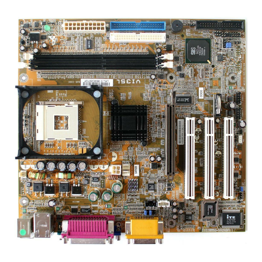
Page 12: Quick Reference (From Page 2-2 To 2-4)
VI35VL Mainboard Manual Quick Reference (from Page 2-2 to 2-4) Mainboard Layout * When link to Line_Out jack, please use a speaker that with amplifier. * Connector Serial IRQ is for system integration use. 2 - 2... -
Page 13: Clear Cmos, Clear Password, Bios Write Protect
Installation Procedures (1). Clear CMOS, Clear Password, BIOS Write Protect (2). Front Panel Block Cable Connection 2 - 3... -
Page 14: Cpu Fan Installation
VI35VL Mainboard Manual (3). CPU Fan Installation Without sufficient air circulation, the CPU This connector is linked to the CPU fan. may overheat resulting in damage to both the CPU and the mainboard. Damage may occur to the mainboard and/or the CPU fan if these pins are used incorrectly. -
Page 15: Bios Write Protect: Bios_P
Installation Procedures (5) Turn off your computer (6) Move the jumper cap pinpair 1-2 to disable this function (7) Turn on your computer for the new settings to take effect. BIOS Write Protect: BIOS_P The board provides users with a jumper for BIOS write protect. To short the jumper will allow users to write BIOS ROM. -
Page 16: Install Memory Modules
VI35VL Mainboard Manual 2). Install Memory Modules 1. Locate the DDR DIMM slots on the mainboard. Install the DDR DIMM straight down into the slot using both hands. 3. The clip on both ends of the slot will close up to hold the... -
Page 17: Install Expansion Cards
Installation Procedures Place the CPU in the socket. Do not force the chip. The CPU should slide easily into the socket. Swing the lever to the down position to lock the CPU in place. Place the cooling fan with heatsink on top of the installed CPU. NOTE: Users The CPU installing procedures should be: 1. - Page 18 VI35VL Mainboard Manual To install an expansion card, follow the steps below: Remove the computer chassis cover and select an empty expansion slot. Remove the corresponding slot cover from the computer chassis. Unscrew the mounting screw that secures the slot cover and pull the slot cover out from the computer chassis.
-
Page 19: Connect Devices
Installation Procedures 5). Connect Devices Floppy Drive Connector This connector provides the connection with your floppy disk drive. The red stripe of the ribbon cable must be the same side with the Pin 1. IDE Device Connectors These two connectors are used for your IDE hard disk drives, CD drives, LS- 120|drives, or IDE ZIP drives. -
Page 20: Power Connectors
VI35VL Mainboard Manual Power Connectors The 20-pin male block connector is connected to the ATX power supply. The 4-pin male block connector is for the 12V power use. The connectors are linked with your ATX power supply. The plug from the power supply will only insert in one orientation because of the different hole sizes. -
Page 21: Cd Audio-In Connectors
Installation Procedures CD Audio-In Connectors The connectors, CD_IN and AUX_IN, are for CD-ROM drive audio analog input use. Front Panel Block, Power LED, IR, and Speaker Connector This block connector includes the connectors for linking with Power LED, HDD LED, power button, power/sleep/message waiting button, reset buttonon the front panel of the system case. - Page 22 VI35VL Mainboard Manual (1) Reset Switch is connected to the reset button. Push this switch to reboot the system instead of turning the power button off and on. (2) HDD LED is connected to the IDE device indicator. This LED will blink when the hard disk drives are activated.
-
Page 23: Fan Connectors
Installation Procedures Fan Connectors The two connectors, CPU_FAN, SYS_FAN are linked to the CPU fan, case fan, respectively. CHIP_FAN can be used either with the case fan or North Bridge chip fan. For preventing the system and chip from overheat damage, the fans on this board will keep running when the system in suspend mode. -
Page 24: Wake-On-Ring Connector
VI35VL Mainboard Manual Wake-On-Ring Connector The 2-pin connector allows you to link with your modem card which outputs a WOR singal; the system can be turned on from the power-off status by a remote phone call via the modem card. -
Page 25: Serial Irq Connector
Installation Procedures Serial IRQ Connector This 2-pin connector is used for some system integration use. PS/2 Keyboard and Mouse Connector These two 6-pin female (PS/2 keyboard is purple color and PS/2 mouse is green color) connectors are used for your PS/2 keyboard and PS/2 mouse. Universal Serial Bus Connectors These two black jacks integrated on the edge of the board are used for linking with USB peripheral devices. -
Page 26: Serial Port Connectors
VI35VL Mainboard Manual The figure below is the pin assignment of the USB pinheader. NOTE: About the USB 2.0 driver. if you use- Windows XP + Sevice Pack 1: it offers the driver. Windows XP: download it from Microsoft web site. -
Page 27: Printer Connector
Installation Procedures Printer Connector This 25-pin D-Sub female burgundy-colored connector is attached to your printer. Audio I/O Jacks LINE_OUT (lime) can be connected to headphones or preferably powered speakers. LINE_IN (light blue) allows tape players or other audio sources to be recorded by your computer or played through the LINE_OUT. -
Page 28: Lan Connector
VI35VL Mainboard Manual LAN Connector The LAN jack is used for the network cable plug. Game/MIDI Connector This 15-pin female gold-colored connector allows you to connect game joysticks or game pads. Connect MIDI devices for playing or editing audio. 2 - 18... -
Page 29: Chapter 3 Bios Setup
BIOS Setup Chapter 3 BIOS Setup The mainboard comes with the chip that BIOS that contains the ROM Setup information of your system. (This chip serves as an interface between the processor and the rest of the mainboard components.) This section explains the information contained in the Setup program and tells you how to modify the settings according to your system configuration. - Page 30 VI35VL Mainboard Manual The CMOS Setup screen is displayed above. Each item may have one or more option settings. The system BIOS automatically detects memory size, thus no changes are necessary. Use the arrow keys to highlight the item and then press Enter key to select the value you want in each item.
-
Page 31: Advanced Features Setup
BIOS Setup Floppy 3 Mode Support This is a Japanese standard floppy type drive. The standard stores 1.44 MB in a 3.5 inch diskette. Installed Memory/Memory Bank These three items tell users the information about the installed memory modules, type, and sizes. BIOS Version/BIOS Relese Date/BIOS Implement Guide These three items tell users the information about the BIOS of the com- puter system. - Page 32 VI35VL Mainboard Manual Reset Configuration Data Enabling it to reset the system Extended System Configuration Data (ESCD) when you exit Setup if you have installed a new add-on card and the system reconfiguration has caused such a serious conflict that the operat- ing system can not boot.
-
Page 33: Onboard Device Configuration
BIOS Setup Onboard Device Configuration On-Chip USB Controller Disable this option if you are not using the onboard USB feature. The options are: Disabled, Enabled. On-Chip LAN Controller Allows you to enable or disable the optional LAN function. The options are: Enabled, Disabled. On-Chip Audio Controller Options The three items below allows you to set on-chip audio controller options. -
Page 34: I/O Device Configuration
VI35VL Mainboard Manual I/O Device Configuration Serial Port A/B Allows you to disable the COM1/2 port when it is needed to do so. The options are: Enabled, Disabled. Onboard Serial Port 1/2 If the serial port 1/2 uses the onboard I/O controller, you can modify your serial port parameters. -
Page 35: Hardware Monitor
BIOS Setup Onboard Parallel Port Allows you to select from a given set of parameters if the parallel port uses the onboard I/O controller. The options are: Disabled, 378/IRQ7, 278/IRQ5, 3BC/IRQ7. Parallel Port Mode Allows you to connect with an advanced printer via the port mode it supports. -
Page 36: Power Features Setup
VI35VL Mainboard Manual Power Features Setup After AC Power Failure When the system is shut down owing to the power failure, the system will not be back to power on by itself. This feature allows you to set the system back to which power status of the system when the system power is resumed. -
Page 37: Boot Features Setup
BIOS Setup Boot Features Setup Boot-time Diagnostic Screen This feature allows to be enabled for troubleshooting or other reason. The options are Disabled, Enabled. Quick Boot Mode This feature allows users to disable the quick boot mode for troubleshoot- ing or other reason. The options are Disabled, Enabled. Boot Device Priority This feature will auto detect all hard disks of bootable device on the sys- tem. -
Page 38: Exit Features Setup
VI35VL Mainboard Manual Exit Features Setup Exit Saving Changes After you have made changes under Setup, press Esc to return to the main menu. Move highlight bar to this item and press Enter key, then press Y to change the CMOS Setup.
Need help?
Do you have a question about the VI35VL and is the answer not in the manual?
Questions and answers