
Related Manuals for BUSCH MINK ATEX


Summary of Contents for BUSCH MINK ATEX
- Page 1 MINK ATEX Claw Compressors MM 1104 BPE, MM 1144 BPE MM 1102 BPE, MM 1142 BPE Instruction Manual 0870141683 | A0001_en-US | Original instructions 4/11/2022...
-
Page 2: Table Of Contents
Table of Contents Table of Contents Safety..................................Product Description ............................. Operating Principle ............................. Intended Use ............................... Design Options ..............................2.3.1 Gas Tight Version ..........................2.3.2 Aqua Version............................Accessories................................2.4.1 Temperature Monitoring ........................2.4.2 Pressure Monitoring..........................Optional Accessories............................2.5.1 Inlet Filter ............................... Explanation of ATEX Classification ........................ - Page 3 Table of Contents Technical Data ..............................Oil ................................... EU Declaration of Conformity..........................Instruction Manual MINK MM 1104-1142 BP ATEX_EN_en 3 | 44...
-
Page 4: Safety
Safety Prior to handling the machine, this instruction manual should be read and understood. If anything needs to be clarified, please contact your Busch representative. Read this manual carefully before use and keep for future reference. This instruction manual remains valid as long as the customer does not change anything on the product. -
Page 5: Product Description
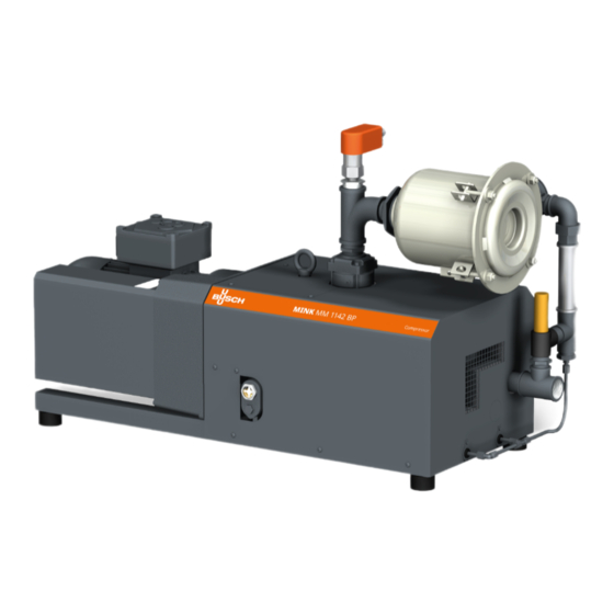
Product Description | 2 Product Description NP-MOT OSG ODP Description Suction connection Discharge connection Oil sight glass Oil drain plug Cooling ait inlet Cooling air outlet Non-return-valve (integrated) Eye bolt Inlet filter (optional) Directional arrow Nameplate Motor terminal box NP-MOT Motor nameplate Terminal box with transmitter Pressure transmitter... -
Page 6: Operating Principle
(NP), see Explanation of ATEX Classification [➔ 9]. The machine is designed for indoor installation, in case of outdoor installation, ask your Busch representative in order to take specific precautions. -
Page 7: Design Options
Product Description | 2 Note: The non-return valve (NRV) is no reliable means to prevent suction and shall not be used as a non-return valve or shut-off valve for the system. If the machine needs to be maintained after shutdown: ●... -
Page 8: Accessories
2 | Product Description Accessories NOTE Depending on the ATEX classification of the machine, some of the following accessories may be mandatory, see ATEX Classifications and Associated Accessories [➔ 10]. 2.4.1 Temperature Monitoring The temperature transmitter (TSA) is to detect high discharge gas temperatures, see Safety Concept [➔ 10]. -
Page 9: Explanation Of Atex Classification
Product Description | 2 Explanation of ATEX Classification The ATEX classification is written on the nameplate of the machine (NP), see below a marking example: Inside (i) II 2G / 3D Ex h IIB TX Gb / IIIC 125°C Dc Outside (o) II Ex h IIB TY Gb / IIIC Description... -
Page 10: Safety Concept
2 | Product Description Safety Concept The safety concept is based on the prevention of sparks and excessive temperatures by means of various accessories. The monitoring devices must be integrated into the system control such that operation of the machine will be inhibited if the safety limit values are exceeded. Temperature Monitoring Temperature transmitter (TSA) is to detect high discharge gas temperatures. -
Page 11: Transport
Transport | 3 Transport WARNING Suspended load. Risk of severe injury! ● Do not walk, stand or work under suspended loads. WARNING Lifting the machine using the motor eye bolt. Risk of severe injury! ● Do not lift the machine using the eye bolt fitted to the motor. Only lift the machine as shown. ●... -
Page 12: Storage
4 | Storage Storage ● Seal all apertures with adhesive tape or reuse provided caps. If the machine is to be stored for more than 3 months: ● Wrap the machine in a corrosion inhibiting film. ● Store the machine indoors, dry, dust free and if possible in original packaging preferably at temperatures between 0 ... -
Page 13: Installation
Installation | 5 Installation Installation Conditions WARNING The installation conditions are not respected in an ATEX environment. Risk of severe injury! Risk of explosion! ● Take care that the installation conditions are met. WARNING Gas tight version: The machine is not absolutely gas tight, possible leakages of dangerous media. Risk of poisoning! Risk of infection! ●... -
Page 14: Connecting Lines / Pipes
● Make sure that all provided covers, guards, hoods, etc. are mounted. If the machine is installed at an altitude greater than 1000 meters above sea level: ● Contact your Busch representative, the motor should be derated or the ambient temperature limited. -
Page 15: Suction Connection
● Make sure that the line size of the connection lines over the entire length is at least as large as the connections of the machine. In case of long connection lines it is advisable to use larger line sizes in order to avoid a loss of efficiency. Seek advice from your Busch representative. 5.2.1 Suction Connection NOTICE Ingress of foreign objects or liquids. -
Page 16: Filling Oil
Use of an inappropriate oil. Risk of premature failure! Loss of efficiency! ● Only use an oil type which has previously been approved and recommended by Busch. For oil type and oil capacity see Technical Data [➔ 38] and Oil [➔ 39]. 16 | 44... -
Page 17: Fitting The Coupling
Installation | 5 Description 4 mm hex key The oil level should stay constant over the lifetime of the oil. If the level does fall, this indicates a leak and the machine requires repair. Fitting the Coupling Description Coupling hub (machine side) Coupling spider Coupling hub (motor side) Set screw;... -
Page 18: Electrical Connection
● Busch recommends installing a D-curve circuit breaker. ● Make sure that the motor of the machine will not be affected by electric or electromagnetic disturbance from the mains; if necessary seek advice from Busch. ● Connect the protective earth conductor. -
Page 19: Wiring Diagram Three-Phase Motor
Installation | 5 NOTICE Incorrect connection. Risk of damage to the motor! ● The wiring diagrams given below are typical. Check the inside of the terminal box for motor connection instructions/diagrams. 5.6.1 Wiring Diagram Three-Phase Motor NOTICE Incorrect direction of rotation. Risk of damage to the machine! ●... -
Page 20: Electrical Connection Of The Monitoring Devices
(middle voltage): Electrical Connection of the Monitoring Devices NOTE In order to prevent potential nuisance alarms, Busch allows that the control system is configured with a time delay of 2 seconds. NOTE The accessories below are considered as standard. -
Page 21: Wiring Diagram Pressure Transmitter
Installation | 5 Electrical data (transmitter): Upper limiting values in supply circuit (certified intrinsically safe electric circuit) = 8 … 30 V DC = 120 mA = 800 mW 4 ... 20 mA ► -20 ... 350 °C Warning signal: a warning signal can be set prior the trip signal. Trip signal: see table below Trip Resistance... -
Page 22: Commissioning
The Aqua version is a design option for conveying condensable vapors (water). Water vapor within the gas flow is tolerated within certain limits. The conveyance of other vapors shall be agreed upon with Busch. If condensable vapors are to be conveyed: Before process: ●... -
Page 23: Maintenance
Risk of injuries! Risk of premature failure and loss of efficiency! ● Maintenance work must only be executed by qualified personnel. ● Respect the maintenance intervals or ask your Busch representative for service. NOTICE Using inappropriate cleaners. Risk of removing safety stickers and protective paint! ●... -
Page 24: Maintenance Schedule
5000 operating hours. Other oils may reduce the change interval. Every 6 years ● Have a major overhaul on the machine (contact Busch). Oil Level Inspection ● Shut down the machine. ● When the machine is stopped, wait 1 minute before checking the oil level. -
Page 25: Cleaning From Dust And Dirt
Maintenance | 7 Cleaning from Dust and Dirt WARNING Explosion of whirled up explosive material or explosive dust. Risk of severe injury! Risk of explosion! Risk of burning! Risk of blown away! ● Avoid any source and situations which can create an ignition spark! ●... -
Page 26: Oil Change
Oil Change NOTICE Use of an inappropriate oil. Risk of premature failure! Loss of efficiency! ● Only use an oil type which has previously been approved and recommended by Busch. 26 | 44 Instruction Manual MINK MM 1104-1142 BP ATEX_EN_en... - Page 27 Maintenance | 7 For oil type and oil capacity see Technical Data [➔ 38] and Oil [➔ 39]. Description 4 mm hex key The oil level should stay constant over the lifetime of the oil. If the level does fall, this indicates a leak and the machine requires repair.
-
Page 28: Pressure Relief Lines Maintenance (Gas Tight Version Only)
7 | Maintenance Pressure Relief Lines Maintenance (Gas Tight Version Only) WARNING Media potentially dangerous. Risk of poisoning! Risk of infection! ● Wear appropriate personal protective equipment in case of high concentration of the medium in the ambient atmosphere of the machine. ●... -
Page 29: Coupling Maintenance
Maintenance | 7 ● Remove the clogging or have the machine repaired (contact Busch). Description Unscrew plugs Connect pressurized air to the pressure relief lines Air pressure max. 0.2 bar (g) Tighten plugs Description Tighten nuts Coupling Maintenance ● Check the coupling backlash and carry out a visual check. - Page 30 7 | Maintenance Manufacturer: KTR Kupplungstechnik Type: ® ROTEX 38/42 ATEX-certified Description Hub (machine side) Clamping screw Coupling spider Set screw Hub (motor side) Radial fan Rotex 38 Rotex 42 13.5 mm 16.0 mm 10.5 mm 12.0 mm ● Remove the motor ●...
-
Page 31: Maintenance Monitoring Devices
Maintenance | 7 Maintenance Monitoring Devices DANGER Live wires. Risk of electrical shock. ● Electrical installation work must only be executed by qualified personnel. NOTICE Incorrect connection. Risk of damage to the motor and temperature switches! ● The wiring diagrams given below are typical. Check the inside of the terminal box for motor and temperature switches connection instructions/diagrams. - Page 32 7 | Maintenance ● Interrupt the ohmic resistance ● Make sure that a fault indication is released in the system control and the machine is shut down automatically ● Reconnect the variable ohmic resistance ● Switch on the machine again ●...
-
Page 33: Overhaul
● Decontaminate the machine as much as possible and state the contamination status in a ‘Declaration of Contamination’. Busch will only accept machines that come with a completely filled in and legally binding signed ‘Declaration of Contamination’ (form downloadable from www.buschvacuum.com). -
Page 34: Decommissioning
9 | Decommissioning Decommissioning DANGER Live wires. Risk of electrical shock. ● Electrical installation work must only be executed by qualified personnel. CAUTION Hot surface. Risk of burns! ● Prior to any action requiring touching the machine, let the machine cool down first. ●... -
Page 35: Spare Parts
Use of non-Busch genuine spare parts. Risk of premature failure! Loss of efficiency and ATEX compliance! ● The exclusive use of Busch genuine spare parts and consumables is recommended for the correct functioning of the machine and to validate the warranty. Spare part Description Part no. -
Page 36: Troubleshooting
11 | Troubleshooting Troubleshooting DANGER Live wires. Risk of electrical shock. ● Electrical installation work must only be executed by qualified personnel. CAUTION Hot surface. Risk of burns! ● Prior to any action requiring touching the machine, let the machine cool down first. Description Inlet screen Coupling... - Page 37 Technical Data [➔ 38]. Oil level too low. ● Top up oil. For the solution of problems not mentioned in the troubleshooting chart contact your Busch representative. Instruction Manual MINK MM 1104-1142 BP ATEX_EN_en 37 | 44...
- Page 38 Weight approx. (50Hz/60Hz) ~190 … 240** ~220 … 235** * In case of higher or lower temperatures, please consult your Busch representative. ** The weight can vary depending on the order. 38 | 44 Instruction Manual MINK MM 1104-1142 BP ATEX_EN_en...
- Page 39 Oil | 13 VS 150 VSB 100 ISO-VG Part number 1 L packaging 0831 164 883 0831 168 351 Part number 5 L packaging 0831 164 884 0831 168 352 Remark Standard oil for non-demanding applications To know which oil has been filled in the machine, please refer to the nameplate (NP). Instruction Manual MINK MM 1104-1142 BP ATEX_EN_en 39 | 44...
- Page 40 14 | EU Declaration of Conformity EU Declaration of Conformity This Declaration of Conformity and the CE-markings affixed to the nameplate are valid for the machine within the Busch scope of delivery. This Declaration of Conformity is issued under the sole responsibility of the manufacturer.
- Page 41 Notes Instruction Manual MINK MM 1104-1142 BP ATEX_EN_en 41 | 44...
- Page 42 42 | 44 Instruction Manual MINK MM 1104-1142 BP ATEX_EN_en...
- Page 43 Instruction Manual MINK MM 1104-1142 BP ATEX_EN_en 43 | 44...
- Page 44 With a network of over 60 companies in more than 40 countries and agencies worldwide, Busch has a global presence. In every country, highly competent local personnel delivers custom-tailored support backed by a global network of expertise. Wherever you are.
Need help?
Do you have a question about the MINK ATEX and is the answer not in the manual?
Questions and answers