
Related Manuals for BUSCH MINK MA 0018 A


Summary of Contents for BUSCH MINK MA 0018 A
- Page 1 Instruction Manual MINK Claw Compressors MA 0018 A 0870153444/A0006_en / Original instructions / Modifications reserved 18/06/2021...
-
Page 2: Table Of Contents
Table of Contents Table of Contents 1 Safety ............................3 2 Product Description ........................4 2.1 Operating Principle ......................4 2.2 Application........................5 3 Transport ..........................5 4 Storage .............................5 5 Installation..........................6 5.1 Installation Conditions ...................... 6 5.2 Connecting Lines / Pipes ....................7 5.2.1 Suction Connection .................... -
Page 3: Safety
Safety Prior to handling the machine, this instruction manual should be read and understood. If anything needs to be clarified, please contact your Busch representative. Read this manual carefully before use and keep for future reference. This instruction manual remains valid as long as the customer does not change anything on the product. -
Page 4: Product Description
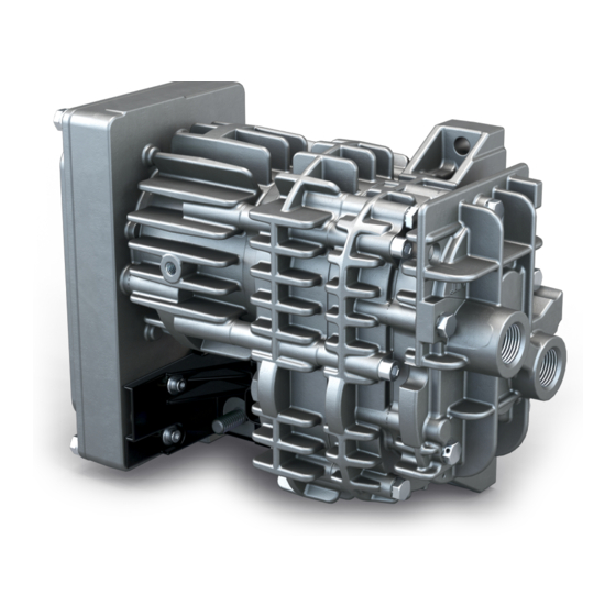
2 | Product Description Product Description 6-pole HDSCS connector (CAN) Electrical connection (+V Batt Inlet connection Nameplate Pressure connection NOTE Technical term. In this instruction manual, we consider that the term ‘machine’ refers to the ‘com- pressor’. NOTE Illustrations In this instruction manual the illustrations may differ from the machine appearance. 2.1 Operating Principle The machine works on the claw principle. -
Page 5: Application
Conveying of other media leads to an increased thermal and/or mechanical load on the machine and is permissible only after a consultation with Busch. The machine is intended for the placement in a non-potentially explosive environment. -
Page 6: Installation
5 | Installation Installation 5.1 Installation Conditions NOTICE Use of the machine outside of the permitted installation conditions. Risk of premature failure! Loss of efficiency! • Take care that the installation conditions are fully complied with. Fixing points • Make sure that the environment of the machine is not potentially explosive. •... -
Page 7: Connecting Lines / Pipes
Busch representative to discuss the corresponding levels. If the machine is installed at an altitude greater than 1000 meters above sea level: • Contact your Busch representative, the motor should be derated or the ambient temperature limited. -
Page 8: Discharge Connection
• Electrical installation work must only be executed by qualified personnel. • Make sure that the motor of the machine will not be affected by electric or electro- magnetic disturbance from the mains; if necessary seek advice from Busch. • Electrically connect the machine... -
Page 9: Version With Analogue Speed Control
Installation | 5 5.3.1 Version with Analogue Speed Control 1 = 0 … 5 V (= 0 … 6600 rpm) 4 = - 2 = - 5 = - 3 = - 6 = - 5.3.2 Version with CAN-Communication 1 = KL15 (20-32VDC) 4 = +5V supply for Mass Flow Sensor (op- tional) 2 = CAN H... -
Page 10: Motor Rotation Direction
6 | Commissioning 5.3.3 Motor Rotation Direction Commissioning NOTICE Lubricating a dry running machine (compression chamber). Risk of damage to the machine! • Do not lubricate the compression chamber of the machine with oil or grease. CAUTION During operation the surface of the machine may reach temperatures of more than 70°C. -
Page 11: Standard Version
Commissioning | 6 6.1 Standard Version The machine starts automatically with maximum speed as soon as electrical power is supplied. 6.2 Version with Analogue Speed Control The electronic is automatically activated as soon as electrical power is supplied. The speed can be controlled by a potentiometer connected to terminal 1 (KL15) on the HDSC connector (CON). - Page 12 6 | Commissioning High voltage level on terminal 1 (KL15) switches on the internal power supply of the ma- chine. After switching on, the machine waits 10 seconds for a valid CAN control message before a CAN failure will be detected. In case of a voltage level below 1.2V on terminal 1 (KL15) the machine decelerates to a speed of 1800 min .
-
Page 13: Maintenance
Maintenance | 7 One second after the stop of the motor the electronic tries to restart the motor automat- ically. If the overcurrent error occurs one more time, the motor stops again and the error bit in the can status frame stays on. Plausibility check A blocked rotor cannot be detected under all conditions by an overcurrent detection. -
Page 14: Oil Draining
7 | Maintenance Interval Maintenance work Every 12000 hours, at the least • Replace the machine. after 6 years 7.2 Oil Draining 7.2.1 Overall Information NOTE Oil draining. Recommendation. • There is no ideal angle to put the gear for oil draining. We would recommend to move the gearbox several times from standard “vertical position”... -
Page 15: Draining Procedure
• Before proceeding the oil draining, make sure that the cylinder of your machine has four access holes to the motor screws. If not, do not proceed the oil draining and con- tact your Busch representative. STEP 1 • Remove the machine from the system. - Page 16 7 | Maintenance STEP 4 NOTE Oil draining. Recommendation. • There is no ideal angle to put the gear for oil draining. We would recommend to move the gearbox several times from standard “vertical position” to a 90° position. The re- maining oil must be the lowest possible.
- Page 17 Maintenance | 7 STEP 5 • 1. Check the surface cleanliness for oil traces. NOTICE Cleaning the surface. Risk of damage to the machine! • Do not use any solvant or liquid. Use only clean and dry paper or tissue! •...
- Page 18 7 | Maintenance STEP 6 • Replace the old motor nose O-ring by the new one delivered in the kit. Put grease on it then place it correctly in its groove. 18 / 36 0870153444_MA0018A_A0006_IM_en...
- Page 19 Maintenance | 7 STEP 7 NOTICE Inserting the stage into the motor. Risk of damage to the machine! • Take care and make sure not to shock or bump the stage while inserting it into the motor! • Insert gently the stage into the motor. Then insert and tighten the four M6 screws with a 5 Nm (+/-10%) screwing torque.
-
Page 20: Service Kit And Oil Type
7 | Maintenance 7.2.3 Service Kit and Oil Type Service Kit – Part number: 0990221163 – Content: Oil filling plug + Motor nose O-ring Oil Type – Fuchs Renolin Unisyn OL32 Oil has to be purchased locally by sales companies because of oil packaging. 20 / 36 0870153444_MA0018A_A0006_IM_en... -
Page 21: Machine Stage Replacement
Maintenance | 7 7.3 Machine Stage Replacement 7.3.1 Stage Disassembly STEP 1 • If the cylinder has four holes to directly access to the motor screws, unscrew them us- ing an M5 hexagonal tool and switch to STEP 4. If not, follow the instructions de- scribed on STEPS 2 and 3. - Page 22 7 | Maintenance STEP 4 • Hold the motor while pulling up the stage (because of the resistance coming from the rotor’s magnetic force). STEP 5 • 1. Check the surface cleanliness for oil traces. NOTICE Cleaning the surface. Risk of damage to the machine! •...
- Page 23 Maintenance | 7 • 2. Remove the existing O-Ring carefully to avoid damaging the groove. • Make sure there is no burr on machined surfaces (chamfer, groove, flange surface, etc.). STEP 6 • Peel the label off (located on the backside of the motor). Do not use temperature higher than 100°C to help removing the label.
-
Page 24: Stage Replacement Package
7 | Maintenance 7.3.2 Stage Replacement Package The new stage is delivered with a kit in a plastic bag including a label with Serial Num- ber. This label must follow the stage to maintain the traceability. The plastic bag kit content is the following: •... - Page 25 Maintenance | 7 STEP 3 NOTICE Inserting the stage into the motor. Risk of damage to the machine! • Take care and make sure not to shock or bump the stage while inserting it into the motor! • Insert gently the stage into the motor. Then insert and tighten the four M6 screws with a 5 Nm (+/-10%) screwing torque.
-
Page 26: Stage Testing
7 | Maintenance 7.3.4 Stage Testing Motor start test: 100% of stages are tested at the manufacturing company and performances are stored for traceability. This test intends to guarantee that the complete blower starts properly. • Use a stabilized 500 Watts power supply. •... -
Page 27: Overhaul
• Decontaminate the machine as much as possible and state the contamination status in a ‘Declaration of Contamination’. Busch will only accept machines that come with a completely filled in and legally binding signed ‘Declaration of Contamination’ (form downloadable from www.buschvacuum.com). -
Page 28: Spare Parts
Risk of premature failure! Loss of efficiency! • The exclusive use of Busch genuine spare parts and consumables is recommended for the correct functioning of the machine and to validate the warranty. Standard spare parts kits are available for this product. -
Page 29: Can Protocol
CAN Protocol | 11 11 CAN Protocol 11.1 Standard CAN Interface 250 kBit/s 0870153444_MA0018A_A0006_IM_en 29 / 36... -
Page 30: Can Interface 500 Kbit/S
11 | CAN Protocol 11.2 CAN Interface 500 kBit/s • Baudrate 500 kb/s • Bit length 11 bit • Behaviour at CAN loss: "0" RPM • Enable signal for electronics activation "Yes" • Motor behaviour when flow request "0" → "Motor waits for signal" •... - Page 31 CAN Protocol | 11 11.5 CAN Interface 250 kBit/s, DOT Purple • Baudrate 250 kb/s • Bit length 29 bit • Behaviour at CAN loss: "0" RPM • Enable signal for electronics activation "No" • Motor behaviour when flow request "0" → "Motor waits for signal" •...
-
Page 32: Technical Data
100 0/+5 Oil leak rate mL/1000hours Dimensions 249.5 x 120 x 199 Weight approx. High frequency transient phases (with up and down pressure levels) need to be discussed and validated between customers and Busch on applications themselves. 32 / 36 0870153444_MA0018A_A0006_IM_en... -
Page 33: Eu Declaration Of Conformity
This Declaration of Conformity and the CE-mark affixed to the nameplate are valid for the machine within the Busch scope of delivery. This Declaration of Conformity is issued under the sole responsibility of the manufacturer. When this machine is integrated into a superordinate machinery the manufacturer of the superordinate machinery (this can be the operating company, too) must conduct the conformity assessment process for the superordinate machine or plant, issue the Declaration of Conformity for it and affix the CE-mark. -
Page 34: Declaration Of Conformity
This Declaration of Conformity and the UKCA-mark affixed to the nameplate are valid for the machine within the Busch scope of delivery. This Declaration of Conformity is issued under the sole responsibility of the manufacturer. When this machine is integrated into a superordinate machinery the manufacturer of the superordinate machinery (this can be the operating company, too) must conduct the conformity assessment process for the superordinate machine or plant, issue the Declaration of Conformity for it and affix the UKCA-mark. - Page 35 Note...
- Page 36 Busch Vacuum Solutions We shape vacuum for you. Argentina Denmark Malaysia South Africa info@busch.com.ar info@busch.dk busch@busch.com.my info@busch.co.za Australia Finland Mexico Spain sales@busch.com.au info@busch.fi info@busch.com.mx contacto@buschiberica.es Austria France Netherlands Sweden busch@busch.at busch@busch.fr info@busch.nl info@busch.se Bangladesh Germany New Zealand Switzerland sales@busch.com.bd info@busch.de sales@busch.co.nz...
Need help?
Do you have a question about the MINK MA 0018 A and is the answer not in the manual?
Questions and answers