
Subscribe to Our Youtube Channel
Related Manuals for Enertech Nu-Way MGN 190 T1L


Summary of Contents for Enertech Nu-Way MGN 190 T1L
- Page 1 Installation & Maintenance Manual MGN 190 T1L (BG300-2) Gas Burner 11/12 Tel: +44 (0) 1905 794331 Fax: +44 (0) 1905 794017 Email: info@nu-way.co.uk Web: www.nu-way.co.uk...
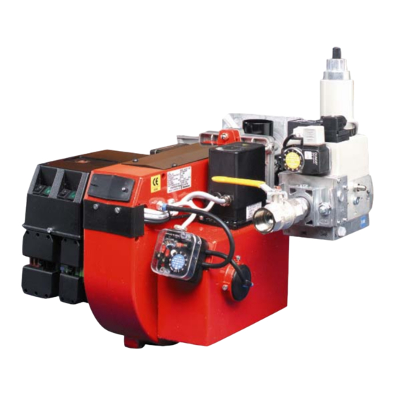
- Page 2 DESCRIPTION COMPONENTS 1. Switch 0-1 8. Flame cone 16. Fan wheel 2. Switch I-II 9. Connection gas fittings 17. Motor 3. Cover, inspection glass 10. Air damper 18. Ionization electrode 4. Reset button 11. Air intake 19. Transformer 5. Air pressure switch 12.
-
Page 4: Technical Data
TECHNICAL DATA DIMENSIONS OF FLANGE ø120 172 215 29 95-01... - Page 5 SKELETON DIAGRAMS, 2-STAGE- OR MODULATING BURNERS Incorporated in the MultiBloc 6b. Safety valve 1. Ball valve Pos. 5b, 7: Components not required 7. Valve proving system 2. Filter according to EN 676. 8. Air damper motor 3. Governor 9. Air pressure switch 4.
-
Page 6: Mounting On The Boiler
MOUNTING ON THE BOILER Remove the combustion unit from the INSTALLATION EXAMPLE REMOVAL OF FAN HOUSE UNIT burner. Fit the enclosed flange and FROM BURNER. Connect the gas to the burner by gasket to the boiler.If new fixing holes Loosen the screws. Swing out the fan means of the ball valve. - Page 7 ELECTRIC EQUIPMENT GAS BURNER CONTROL: LMG22.../LGB22... WIRING DIAGRAM COMPONENT LIST A1 Gas burner control B1 Ionization electrode F1 Fuse H1 Lamp, low capacity H2 Lamp, high capacity H3 Alarm signal 220 V M1 Burner motor M2 Damper motor, L&S SQN75.254.A21B P1 Time meter, total operating time P2 Time meter, high capacity time S1 Operating switch...
-
Page 8: Electric Equipment
ELECTRIC EQUIPMENT GAS BURNER CONTROL : LMG222…/LGB22… FUNCTION 1. Operating switch On – Thermostat On – gas pressure switch ON – Air damper closed A control is made that the air pressure switch does not indicate fan pressure. Then the burner motor starts. 2. - Page 9 EXTERNAL WIRING CONNECTIONS FOR MGN SERIES BURNERS 3PH SUPPLY MPA HIGH/LOW BLACK BROWN/BLACK GAS TRAIN BROWN MPA TLK MOD GREEN VALVE PROVING BROWN/BLACK BLACK MODULATING Note: Control Loop is via Alarm 1 in TLK Control For Modulating remove plug-in loose WATER TEMP.
- Page 10 ELECTRIC EQUIPMENT CONTROL DIAGNOSIS UNDER FAULT CONDITIONS AND LOCKOUT INDICATION GAS BURNER CONTROL: LMG ... Operating concept • Burner control has initiated lockout • Reset > Red fault LED on Press lockout reset button for 0.5 ...3 s • Diagnosis of cause of fault - Wait >10 s - Press lockout reset buttonj for >3 s - Read blink code of red fault LED...
- Page 11 GAS BURNER CONTROL: LMG ... Interrogation of flame es- This function measures the flame establishment time with ionization supervision. With the tablishment time AGQ2..., this function cannot be used. In the running position, the green flame signal LED is steady on. The flame establishment time is read in the running position according to the following sequence: Press lockout...
- Page 12 MEASURES AND CHECKS BEFORE START-UP, 2-STAGE- OR MODULATING BURNERS INNER ASSEMBLY NOTE! APPLIES ONLY TO GAS LEAKAGE CONTROL Ensure that the ignition and ionisa- BURNER CONTROL LFL1. MultiBloc tion electrodes are correctly adjus- When using LPG (Propane) the bur- ted. The sketch shows the correct ner should be connected for post- measurements.
- Page 13 MEASURES AND CHECKS BEFORE START-UP INNER ASSEMBLY Town gas INNER ASSEMBLY Natural gas, LPG Natural gas INNER ASSEMBLY Biogas (UV-detector) 172 205 78 98-01...
- Page 14 DETERMINATION OF GAS VOLUME FOR THE INSTALLATION Specifications on natural gas, town Net calorific value gas and bio gas vary. For more exact information please contact the gas Gas quality kWh/Nm kJ/Nm kcal/Nm distributor. Natural gas 10.3 37 144 8 865 Propane 26.0 93 647...
-
Page 15: Air Adjustment
FUNCTION, 2-STAGE DESIGN AIR ADJUSTMENT The damper motor turns the damper between three pre-set positions: fully closed, low load, full load. These positons are controlled in the motor by cams of different colours. The black cam controls the gas valve for full load. If the air volume needs changing: Remove the cover of the damper motor and change the position of the cams by turning them with the tools accompanying the burner. - Page 16 MULTI-BLOC, MB-ZRDLE 405-420 Max. inlet pressure: 360 mbar. 1. Ball valve Adjustable governor pressure: 2. Fixing flange 405 - 412 S50 = 4 - 50 mbar 3. Gas pressure switch 415 - 420 S20 = 4 - 20 mbar 4. Governor with pressure adjust- 415 - 420 S50 = 20 - 50 mbar ment Solenoid valve: Slow opening valves...
-
Page 17: Flow Adjustment
ADJUSTMENT OF MULTI-BLOC, MB-ZRDLE 405-420 FLOW ADJUSTMENT ADJUSTMENT OF GOVERNOR ADJUSTMENT OF START GAS 2-STAGE DESIGN Adjust outlet pressure from governor FLOW For stage 1, loosen the lock screw a. by means of a screw driver. Min. and Remove the protective cover c. Turn the hydraulic device e: max. -
Page 18: General Instructions
GENERAL INSTRUCTIONS ADJUSTMENT OF BURNER SERVICE Service should only be carried out by The burner is from the factory pre-set A general rule is that the lower capa- qualified personnel. Replacement to an average value that must then be city the smaller the opening between parts should be of the same make adjusted to the boiler in question. - Page 19 GENERAL INSTRUCTIONS ADJUSTMENT OF BRAKE PLATE Loosen the screw on the adjust- ment device. To reduce the opening: turn the knob to the left. To increase the opening: turn the knob to the right. The adjustment of the position of the brake plate affects the air flow.
-
Page 20: General Instruction
GENERAL INSTRUCTION ADJUSTEMNT OF MAX. GAS PRES- ADJUSTMENT OF AIR PRESSURE FLAME MONITORING AND MEASU- SURE SWITCH SWITCH REMENT OF IONISATION CURRENT The burner is equipped with a max. gas The air presure switch should stop the The burner is monitored according to pressure switch only on request. -
Page 21: Handing Over Of The Installation
HANDING OVER OF THE INSTALLATION Make repeated start attempts to FAULT LOCATION, FUNCTIONAL ensure that the adjustments func- TROUBLES tion. Trouble free operation is dependent on three factors: electricity, gas and air Close the ball valve during opera- supply. Should there be any changes tion to check that the gas switch in the ratio between these three factors switches off at the set value. - Page 22 FAULT LOCATION GUIDE Gas burner The basis for trouble free operation can only be ensured To facilitate fault location we have drawn up a scheme by the correct combined effect of the three factors: showing the most frequent faults in a gas burner instal- electricity, gas flow and combustion air.
- Page 23 CAUSE REMEDY The cable shoes have bad contact Improve the contact The ignition cables are damaged Replace The ignition transformer is damaged, no voltage on the Replace the transformer secondary side The ignition cable and the ionisation cable have been Change transposed.
- Page 24 CAUSE REMEDY Voltage lower than 185 V Contact the electricity authorities. The ignition electrodes are disturbing the ionisation Adjust the ignition electrodes, repole the ignition transfor- current mer if necessary. Bad earthing Arrange for proper earthing. Phase and neutral transposed See wiring diagram and change.
- Page 25 CAUSE REMEDY The ambient temperature of the gas relay is too high Heat insulate, max. 60° C. The ignition spark is too weak Check the transformer Bad combustion Bad draught conditions Check the chimney The flue gas temperature is too high The boiler is overloaded.
- Page 26 NOTES...
- Page 27 Enertech Limited, P O Box 1, Vines Lane Droitwich, Worcestershire, WR9 8NA Tel: +44 (0) 1905 794331 Fax: +44 (0) 1905 794017 Email: info@nu-way.co.uk Web: www.nu-way.co.uk...
Need help?
Do you have a question about the Nu-Way MGN 190 T1L and is the answer not in the manual?
Questions and answers