
Related Manuals for urmet domus BASIC 1062/341


Summary of Contents for urmet domus BASIC 1062/341
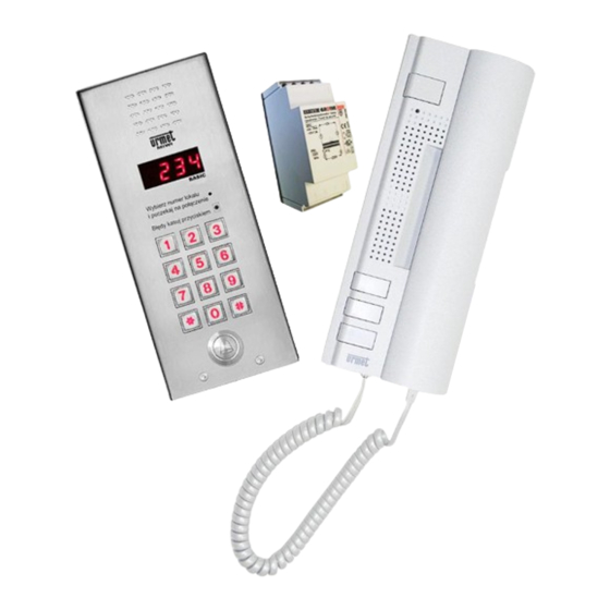
- Page 1 DIGITAL DOORPHONE SYSTEM INTERCOM SET 1062/341 20.06.2016 Software version: BASIC 1.19...
-
Page 2: Technical Data
INTERCOM SET REF. NO. 1062/341 DIGITAL CALL MODULE WITH KEYBOARD TECHNICAL DATA REF. NO. 1062/1VD From dedicated power supply Power supply: GT1975 Control of electrical lock: With built-in current control -20 C +50 C Operating temperature: Dimension (H x W x D): 23÷35 [mm] (nr ref. - Page 3 INTERCOM SET REF. NO. 1062/341 USER MANUAL OPENING THE DOOR (CONTACT +C –C) WITH CODES DESCRIPTION OF TERMINAL BOARDS We are able to open the door using one of 64, 4-digits general KEYBOARD MODULE opening codes. To do it: Input voltage + 18 V DC. ...
-
Page 4: Grey Background
INTERCOM SET REF. NO. 1062/341 PROGRAMMING PROGRAMMING P 2. 0 1 In BASIC system, to simplify installation, call modules are provided with preconfigured settings: Call codes within 1 to 100 range, Press to confirm. To all call codes are assigned random individual opening codes, Idle time in programming mode is 120 s. - Page 5 INTERCOM SET REF. NO. 1062/341 PROGRAMMING LUx line contact configuration Adding Dallas key to the user. Identifying / Deleting of Dallas key. Stop time. Identifying / Deleting of Dallas key (according to Interruption time after stop. logical code – without Dallas key). Length of address impulse.
- Page 6 INTERCOM SET REF. NO. 1062/341 PROGRAMMING 1.06 MINIMAL LENGTH OF OPENING IMPULSE [ms] 1. LUx LINE CONTACT CONFIGURATION Please do not change these parameters until necessary, for P 1. 0 6 example: cannot call specific doorphone. Before this please eliminate all other causes. 1.01 STOP TIME [ms] In this step you can change minimal length of opening impulse (opening impulse is an impulse which causes opening the door -...
-
Page 7: Global Settings
INTERCOM SET REF. NO. 1062/341 PROGRAMMING 1.10 LEVEL OF CURRENT FOR SHORT-CIRCUIT DETECTION 2. GLOBAL SETTINGS [mA] 2.01 CALL CODE CONFIRMATION P 1. 1 0 P 2. 0 1 In this step you can change level of the current for short-circuit (value of the current at which system detects short-circuit in LU In this step you can set parameter responsible for 1 of 2 ways to call:... - Page 8 CALL MODULES PROGRAMMING 2.05 ADDITIONAL RING DURING PICK-UP TIME Press and hold button to save value. P 2. 0 5 Default setting - 20 2.10 MAXIMAL CONVERSATION LENGTH TIME In this step we can turn on an additional call signal (after main call P 2.
- Page 9 CALL MODULES PROGRAMMING 3.04 ELECTRICAL LOCK MODE 3. EI/OC/DOOR/PS CONFIGURATION 3.01 FREQUENCY OF ELECTRICAL LOCK P 3. 0 4 P 3. 0 1 In this step we can set electrical lock mode. The options are: In this step we can set frequency of electrical lock which is attached to +C –C terminals in keyboard.
- Page 10 CALL MODULES PROGRAMMING THEN DEFAULT "1"). THIS NUMBER WILL REFLECT ON THE 3.10 OC1 SETTINGS LED DISPLAY DURING THE CALL. IT CAN BE NUMBER OF YOUR YARD OBJECT (THE SCOPE 1-255). REMEMBER TO P 3. 1 0 SET THE SAME PHYSICAL ADDRESS In DOORPHONE USING JUMPERS (DEFAULT ADRESS IS "1").
- Page 11 CALL MODULES PROGRAMMING We can assign call code (logical code) to every possible jumper P 3. 1 2 setting in doorphone (physical code). To do it: Enter physical code of doorphone, PS output is a generator output. In order to use generator it is ...
- Page 12 CALL MODULES PROGRAMMING 4.03 CHANGE / PROGRAMMING OF GENERAL OPENING CODES P 4. 0 3 4.05 IDENTIFYING / DELETING OF DALLAS KEY (WITH DALLAS KEY) In this step we can identify or delete the Dallas key (with Dallas key It is possible to program up to 64 general opening codes which can use).
-
Page 13: Memory Edit
CALL MODULES PROGRAMMING 5.07 RESTORE INDIVIDUAL OPENING CODES 5. MEMORY EDIT 5.01 DELETE LOGICAL CALL CODES P 5. 0 7 P 5. 0 1 To activate this function press button. To activate this function press button. This function will restore factory settings of individual opening codes This function will affect global –... -
Page 14: Service Functions
CALL MODULES PROGRAMMING Example 6. SERVICE FUNCTIONS To shift address by 1 (doorphone with physical address 1 match 6.01 EDIT AND CHANGING ENTER PASSWORD logical code 2, doorphone with physical address 2 match logical code 3, etc.): P 6. 0 1 ... -
Page 15: Additional Functions
CALL MODULES PROGRAMMING 6.05 AUTOMATIC OPENING AFTER LOGICAL (CALL) CODE 6.10 INDIVIDUAL SETTINGS RESET CONFIRMATION IN CASE OF MALFUNCTION P 6. 1 0 P 6. 0 5 Use this function to restore global and factory setting to the This option allows for automatic electrical lock release after call, in parameters which can be modified by user. -
Page 16: Error Messages
INTERCOM SET REF. NO. 1062/341 ERROR MESSAGES / ADJUSTMENT WALL MOUNTED VERSION ERROR MESSAGES Take the front panel off. All call modules with keyboard detects and identify errors occurred Disconnect the terminal block from signal connector. in system. Relevant error message (with error code) is shown on Fit the cable through the hole B located in back part. -
Page 17: Basic Features
DOORPHONE WITH ADDITIONAL BUTTON REF. NO. 1134/622 GENERAL INFORMATIONS / TECHNICAL DATA Doorphone can be programmed using jumpers. Number from 1 to DOORPHONE WITH ADDITIONAL BUTTON 127 (connector X1) can be set. It is a physical address of the REF. NO. 1134/622 doorphone. -
Page 18: Technical Specification
POWER SUPPLY REF. NO. GT1975 GENERAL INFORMATIONS / TECHNICAL DATA POWER SUPPLY REF. NO. GT1975 GENERAL INFORMATION Power supply GT1975 used to power the SET INTERCOM BASIC DESCRIPTION OF TERMINAL BOARDS Main supply (230 V AC) Main supply (230 V AC) Output supply terminal 12 V AC Output supply terminal 12 V AC TECHNICAL SPECIFICATION... - Page 19 SCHEME BASIC CONFIGURATION...
- Page 20 SCHEME CONFIGURATION WITH RELAY REF. NO. 788/52...
- Page 21 NOTES...
- Page 22 NOTES...
- Page 23 NOTES...
- Page 24 MIWI-URMET Co. Ltd. Pojezierska 90A 90-341 Lodz, Poland tel: 004842 616 21 00 fax: 004842 616 21 13 e-mail: miwi@miwiurmet.pl http:/www.miwiurmet.pl The symbol of the crossed out wheeled bin indicates that the product (electrical and electronic equipment) should not be placed in municipal waste.
Need help?
Do you have a question about the BASIC 1062/341 and is the answer not in the manual?
Questions and answers