Advertisement
Quick Links
OMNI 291 - User Guide
South Africa
Unit 4, N1 Industrial Park
Landmarks Ave
Samrand, 0157,
South Africa
Tel: +27 12 657 0050
info@poynting.tech
Making wireless happen
Europe
Kronstadler Straße 4,
81677 München
Germany
Tel: +49 89 2080 265 38
Mob.: +49 176 529 733 50
sales-europe@poynting.tech
Version: 4.0
Advertisement

Related Manuals for Poynting OMNI 291


Summary of Contents for Poynting OMNI 291
- Page 1 Making wireless happen OMNI 291 - User Guide South Africa Europe Unit 4, N1 Industrial Park Kronstadler Straße 4, Landmarks Ave 81677 München Samrand, 0157, Germany South Africa Tel: +49 89 2080 265 38 Tel: +27 12 657 0050 Mob.: +49 176 529 733 50 info@poynting.tech...
- Page 2 A-OMNI-0291_PCL...
- Page 3 Index Packing Check List Optional Accessories Introduction Installation Instructions Antenna Mounting Precautions Cable Routing Safety Version: 4.0...
- Page 4 Packing Check List Item Description Quantity A-OMNI-0291 Antenna only M4 Allen Cap Screws Allen key L-Bracket Econo bracket stainless steel M6x60mm U-Bolts stainless steel M6 Nuts/Nylock stainless steel M6 Flat Washers stainless steel Adapter Base Seal Locking nut A-OMNI-0291_PCL...
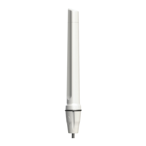
- Page 5 The appearance of each component Antenna Unit Adaptor Base and Seal Stainless steel bracket assembly Allen cap screw,allen key and locking Version: 4.0...
-
Page 6: Optional Accessories
Optional Accessories Optional Accessories A-BRKT-037: Marine flat mount antenna bracket stainless steel AA-BRKT-038: Marine ratchet rail mount antenna bracket stainless steel A-BRKT-039: Heavy duty marine mount antenna bracket stainless steel Splitter 14 A-OMNI-0291_PCL... - Page 7 Introduction This User Guide provides information on the installation instructions of the Omni-directional marine antenna (A-OMNI-0291) Antenna Configuration 1 Pole mount with supplied L-Bracket Exploded View Antenna Configuration 2 Marine mount with optional bracketry using the provided allen key. Exploded View Version: 4.0...
- Page 8 Introduction Antenna Connection Diagram Configuration 1 Connect the antenna to a cellular modem. CELLULAR MODEM Single Port Configuration 2 Connect the antenna to a WiFi access point and a cellular modem using a splitter. SPLITTER CELLULAR MODEM WiFi Single Port A-OMNI-0291_PCL...
-
Page 9: Lte Modem
* When mounting two OMNI 291 antennas in a LTE configuration: Space the antennas as far apart as possible, with a minimum distance of 1.5m Configuration 3 Use two antennas to connect to an LTE modem and a WiFi access point. -
Page 10: Installation Instructions
Installation Instructions • Open the antenna package and confirm that all listed components are available. • Consider the antenna mounting precautions below before installation. Straight cable entry Insert the RF cable assembly through the pipe, seal and adapter base. Assembled Screw the RF cable antenna with connector to the... - Page 11 Larger side cable entry (Drilling/ cutting and filling required) Use a drill bit / holesaw or file to obtain required hole size. Insert the RF cable Assembled an- assembly through tenna with side the knocked out entry cable. section of the adapter base.
-
Page 12: Cable Routing
Antenna Mounting Precautions • Place the antenna at the highest point of the vessel and ensure that there aren’t any surrounding obstructions to the antenna. • In order to avoid communication interference, ensure that the antenna is placed at least 0.5m away from other antennas and metal objects. - Page 13 • Use cable ties to secure the antenna cables. When handling the antenna cables, it is essential you follow these basic rules: • Never pull on the cable connectors; pull only on the cable. • Never run cables in a manner that interferes with the driver’s ability to safely operate the boat.
Need help?
Do you have a question about the OMNI 291 and is the answer not in the manual?
Questions and answers