Table of Contents
Advertisement
Quick Links
FlowCon FN.0.2, FN.0.2-BUS and FN.0.4
1B95080 - 01/2023
Installation and Operation Instruction
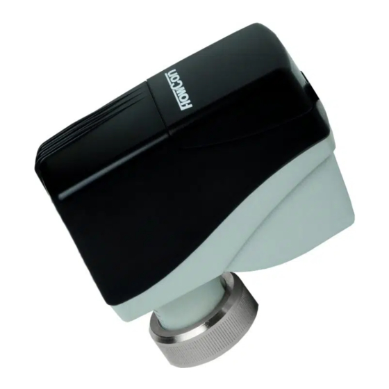
The actuator types FlowCon FN.0.2, FN.0.2-
BUS and FN.0.4 are electrical actuators.
• FN.0.2 is 24V modulating.
• FN.0.2-BUS is 24V modulating with Modbus or
BACnet communication.
• FN.0.4 is 24V 3-point floating and 2-position.
Fitting and Re-fitting
Do not connect power to the actuator unless
the actuator is already fitted on the valve
and NEVER install the actuator in closed
position - this may damage the valve. Actu-
ator is supplied in open position to ensure
easy commissioning of the system.
Mount the actuator on the valve and finger
tighten the connection union. Do not use addi-
tional tools.
In case the actuator will have to be removed, it is
recommended for FN.0.2 and FN.0.4 to electri-
cally open the actuator by activating DIP switch
#6 for easier removal.
For FN.0.2-BUS set DIP switch #1-6 to OFF and
wait until the LED indicator is blinking green.
Hereafter, disconnect power and finger loosen
the connection union. Again, no need for addi-
tional tools. Please make sure that the actuator
is electrically opened, before re-fitting it on the
valve.
This paper is a supplement to the FlowCon General Instruction
Latest release of any FlowCon material is available on www.flowcon.com
Figure 1
Figure 2
Orientation
Upside-down installation is allowed along with
the standard horizontal and vertical installation.
360º
Figure 3
Page 1 of 8
Advertisement
Table of Contents

Related Manuals for FlowCon FN.0.2


Summary of Contents for FlowCon FN.0.2
- Page 1 Upside-down installation is allowed along with #6 for easier removal. the standard horizontal and vertical installation. For FN.0.2-BUS set DIP switch #1-6 to OFF and 360º wait until the LED indicator is blinking green. Hereafter, disconnect power and finger loosen the connection union.
- Page 2 This is the time from giving a 24V power signal until the actuator starts to move. This is particular important if using a pulse power signal. This paper is a supplement to the FlowCon General Instruction Page 2 of 8 Latest release of any FlowCon material is available on www.flowcon.com...
- Page 3 When performing the manually override proce- dure on the FN.0.2-BUS, set DIP switches 1 to 6 to OFF and the spindle will fully retract, and the LED will rapidly blink green. In this state the valve can be manually close or opened using a magnet.
- Page 4 BIT 1 = 1 BIT 1 = 0 BIT 0 = 1 BIT 0 = 0 This paper is a supplement to the FlowCon General Instruction Page 4 of 8 Latest release of any FlowCon material is available on www.flowcon.com...
- Page 5 Manuel spindle adjustment Blinking yellow Perpetual failure mode Full on red Full on red Full on red This paper is a supplement to the FlowCon General Instruction Page 5 of 8 Latest release of any FlowCon material is available on www.flowcon.com...
- Page 6 10V-2V to achieve re-calibration. After re-calibration the actuator will go into normal operation mode. FN.0.2-BUS For FN.0.2-BUS change MSV.1 to 2 (BACnet) or register 138 to 1 (Modbus). After re-calibration the actuator will go into normal operation mode. FN.0.4 Forced individual actuator re-calibration can also be performed by flipping DIP switch #6 from OFF to ON and back to OFF on the relevant actuator.
- Page 7 And select your PICV control mode in register 103 or MSV.13: Reg. 103 MSV.13 Selected control mode (linear) Equal% This paper is a supplement to the FlowCon General Instruction Page 7 of 8 Latest release of any FlowCon material is available on www.flowcon.com...
- Page 8 FlowCon FN.0.2, FN.0.2-BUS and FN.0.4 1B95080 - 01/2023 This paper is a supplement to the FlowCon General Instruction Page 8 of 8 Latest release of any FlowCon material is available on www.flowcon.com...
Need help?
Do you have a question about the FN.0.2 and is the answer not in the manual?
Questions and answers