FlowCon Energy FIT System SM.3 Installation And Operation Instruction Manual
Hide thumbs
Also See for Energy FIT System SM.3:
Table of Contents
Advertisement
Quick Links
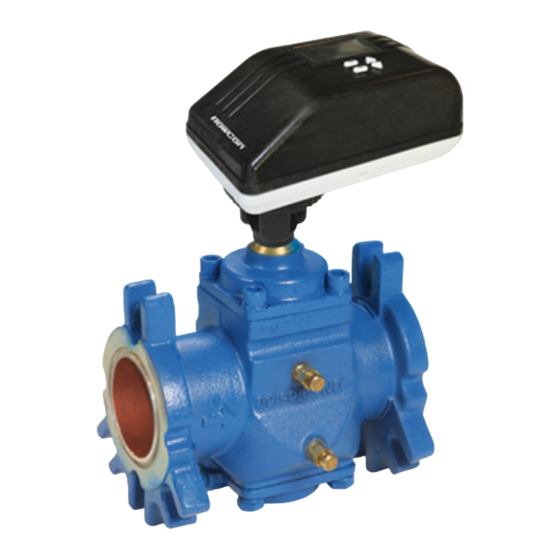
FlowCon FIT 65-250 mm (2 1/2"-10")
1B95095 - 02/2020
Installation and Operation Instruction
The FlowCon Energy FIT System are avail-
able in different sizes and four different flanged
models covering 8 different sizes:
FlowCon SM.3 DN65-80 (2 1/2"-3")
FlowCon SM.4 DN80-100 (3"-4")
FlowCon SM.5 DN125-150 (5"-6")
FlowCon SM.6 DN200-250 (8"-10")
O-rings are supplied with the valve body and are
used to seal the connections. It is recommended
to grease the O-rings with silicone grease.
Please make sure these are properly placed
in the O-ring grooves on valve inlet and outlet,
before installing the housing. Please note that
FlowCon SM.6 (DN200-250 / 8"-10") contains two
O-ring grooves. Use the inner groove for DN200 /
8" flanges and outer groove for DN250 / 10" flanges.
O-ring Groove
200 mm (8")
flanges
O-ring Groove
250 mm (10")
flanges
Figure 1
This paper is a supplement to the FlowCon General Instruction
Latest release of any FlowCon material is available on www.flowcon.com
The actuator types FlowCon SM.0.0.0.3,
SM.0.0.0.4, SM.0.0.0.5 and SM.0.0.0.6 are elec-
trical programmable actuators. SM.0.0.0.5 and
.6 are BACnet actuators and have a supplemen-
tary instruction on BACnet connection and pro-
gramming.
Fitting and Re-fitting the actuator
It is recommended to grease the O-ring on the
spindle adaptor with silicone grease before plac-
ing the spindle adaptor on the valve spindle.
Then place the actuator on the spindle adaptor
and place the three actuator "legs" into the three
holes in the mounting bracket (figure 2 and 3).
Make sure that the snap ring is clicked onto the
mounting bracket, so that the snap ring is locked
at the top of the mounting bracket, but still able to
rotate. Then finger-turn the snap ring counter
clockwise (upside view) approximately 1/6 of a
turn until its stop points touch the actuator "legs"
and the mounting is lock with a (small) click. Do
not use additional tools.
Spindle adaptor
Snap ring
Figure 2
The bottom side of the
actuator
"Actuator
legs"
Snap ring:
Stop points
Figure 3
Page 1 of 10
Advertisement
Table of Contents

Related Manuals for FlowCon Energy FIT System SM.3


Summary of Contents for FlowCon Energy FIT System SM.3
- Page 1 250 mm (10”) flanges “Actuator legs” Snap ring: Stop points Figure 1 Figure 2 Figure 3 This paper is a supplement to the FlowCon General Instruction Page 1 of 10 Latest release of any FlowCon material is available on www.flowcon.com...
- Page 2 Opening cover will void warranty. Remember to remove the protection film from the actuator display to avoid conden- sation. This paper is a supplement to the FlowCon General Instruction Page 2 of 10 Latest release of any FlowCon material is available on www.flowcon.com...
- Page 3 Be aware to connect according to wiring diagrams page 4 and 5 to avoid loosing warranty. This paper is a supplement to the FlowCon General Instruction Page 3 of 10 Latest release of any FlowCon material is available on www.flowcon.com...
-
Page 4: Wiring Instructions
Black ΔP Flow ΔT Green White Black Red (no function) Input signal White 2-10V DC Green This paper is a supplement to the FlowCon General Instruction Page 4 of 10 Latest release of any FlowCon material is available on www.flowcon.com... -
Page 5: Start-Up Sequence
At first start-up please enter programming menu tion mode (according to control signal). to set actuator settings. This paper is a supplement to the FlowCon General Instruction Page 5 of 10 Latest release of any FlowCon material is available on www.flowcon.com... -
Page 6: Programming Menu
Options: 2-10VDC or 4-20mA or digital. Choose: *scrolling top: • 2-10VDC for VDC SELECT CONTROL SIGNAL This paper is a supplement to the FlowCon General Instruction Page 6 of 10 Latest release of any FlowCon material is available on www.flowcon.com... - Page 7 3. Actuator shuts off. If power supply is restored during action 1. or 2., failsafe mode is deactivated. This paper is a supplement to the FlowCon General Instruction Page 7 of 10 Latest release of any FlowCon material is available on www.flowcon.com...
- Page 8 If display shows “NA” the valve model has not been chosen in programming menu step 2. This paper is a supplement to the FlowCon General Instruction Page 8 of 10...
-
Page 9: Alarm Menu
Alarm will reset FULL ON when BACnet control signal is refreshed. Only valid for BACnet actuators. This paper is a supplement to the FlowCon General Instruction Page 9 of 10 Latest release of any FlowCon material is available on www.flowcon.com... -
Page 10: Manual Override
13 and show warning code 05 in the actuator display. When voltage is back ⚠ in range will be reset. This paper is a supplement to the FlowCon General Instruction Page 10 of 10 Latest release of any FlowCon material is available on www.flowcon.com...
Need help?
Do you have a question about the Energy FIT System SM.3 and is the answer not in the manual?
Questions and answers