Table of Contents
Advertisement
Quick Links
FlowCon SM 15-250 mm (1/2"-10")
1A95106 - 01/2019
Installation and Operation Instruction
The FlowCon SM are available in two different
double union end connected models covering five
different sizes and four different flanged models
covering nine different sizes:
FlowCon SM.1 DN15-25 (1/2"-1")
FlowCon SM.2 DN25-40 (1"-1½")
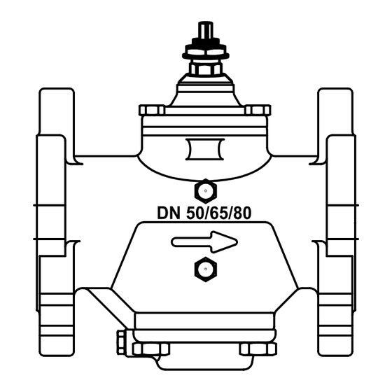
FlowCon SM.3 DN50-80 (2"-3")
FlowCon SM.4 DN80-100 (3"-4")
FlowCon SM.5 DN125-150 (5"-6")
FlowCon SM.6 DN200-250 (8"-10")
DN
25/32/40
O-rings are supplied with the valve body and are
used to seal the connections. It is recommended
to grease the O-rings with silicone grease.
Please make sure these are properly placed
in the O-ring grooves on valve inlet and outlet,
before installing the housing. Please note that
FlowCon SM.6 (DN200-250 / 8"-10") contains two
O-ring grooves. Use the inner groove for DN200 /
8" flanges and outer groove for DN250 / 10" flanges.
O-ring Groove
200 mm (8")
flanges
O-ring Groove
250 mm (10")
flanges
Figure 1
This paper is a supplement to the FlowCon General Instruction
Latest release of any FlowCon material is available on www.flowcon.com
The actuator types FlowCon SM.0.0.0.3,
SM.0.0.0.4, SM.0.0.0.5 and SM.0.0.0.6 are elec-
trical programmable actuators. SM.0.0.0.5 and
.6 are BACnet actuators and have a supplemen-
tary instruction on BACnet connection and pro-
gramming.
Fitting and Re-fitting the actuator
It is recommended to grease the O-ring on the
spindle adaptor with silicone grease before plac-
ing the spindle adaptor on the valve spindle.
Then place the actuator on the spindle adaptor
and place the three actuator "legs" into the three
holes in the mounting bracket (figure 2 and 3).
Make sure that the snap ring is clicked onto the
mounting bracket, so that the snap ring is locked
at the top of the mounting bracket, but still able to
rotate. Then finger-turn the snap ring counter
clockwise (upside view) approximately 1/6 of a
turn until its stop points touch the actuator "legs"
and the mounting is lock with a (small) click. Do
not use additional tools.
Spindle adaptor
Snap ring
Figure 2
The bottom side of the
actuator
"Actuator
legs"
Snap ring:
Stop points
Figure 3
Page 1 of 8
Advertisement
Table of Contents

Related Manuals for FlowCon SM Series


Summary of Contents for FlowCon SM Series
- Page 1 “Actuator 250 mm (10”) legs” Snap ring: flanges Stop points Figure 2 Figure 3 Figure 1 This paper is a supplement to the FlowCon General Instruction Page 1 of 8 Latest release of any FlowCon material is available on www.flowcon.com...
- Page 2 Figure 5 Figure 4 Do not remove cover from actuator. Opening cover will void warranty. This paper is a supplement to the FlowCon General Instruction Page 2 of 8 Latest release of any FlowCon material is available on www.flowcon.com...
-
Page 3: Start-Up Sequence
At first start-up please enter programming menu tion mode (according to control signal). to set actuator settings. This paper is a supplement to the FlowCon General Instruction Page 3 of 8 Latest release of any FlowCon material is available on www.flowcon.com... -
Page 4: Programming Menu
SELECT CONTROL SIGNAL • 4-20mA for mA • Digital for 2 position or 3 point floating. This paper is a supplement to the FlowCon General Instruction Page 4 of 8 Latest release of any FlowCon material is available on www.flowcon.com... - Page 5 Failsafe direction open means SELECT FAIL SAFE DIRECT opening to max. flow chosen in step 9. This paper is a supplement to the FlowCon General Instruction Page 5 of 8 Latest release of any FlowCon material is available on www.flowcon.com...
- Page 6 If display shows “NA” the valve model has not been chosen in programming menu step 2. This paper is a supplement to the FlowCon General Instruction Page 6 of 8...
-
Page 7: Alarm Menu
Alarm will reset FULL ON when BACnet control signal is refreshed. Only valid for BACnet actuators. This paper is a supplement to the FlowCon General Instruction Page 7 of 8 Latest release of any FlowCon material is available on www.flowcon.com... -
Page 8: Manual Override
13 and show warning code 05 in the actuator display. When voltage is back ⚠ in range will be reset. This paper is a supplement to the FlowCon General Instruction Page 8 of 8 Latest release of any FlowCon material is available on www.flowcon.com... -
Page 9: Warranty
Failure to abide by all recommendations as per this General Instruction will void warranty. For any supplementary warranty obligations, plea- se see the relevant product specific installation and operation instruction. Latest release of any FlowCon material is available on www.flowcon.com Page 1 of 4... - Page 10 P/t plugs without collar. The valve is available for double flanged connec- tions for all model sizes. P/t plugs without collar. Latest release of any FlowCon material is available on www.flowcon.com Page 2 of 4...
- Page 11 300 according to ASME B16.5. depending on WILL DAMAGE THE O-RING). If the capillary product ordered. tube is to be mounted in a FlowCon Partner Ball Flanges are not supplied by FlowCon. or other valve with 1/4” (ISO 7/1) tapping, a 1/4”...
- Page 12 FlowCon General Instruction 1B95011 - 01/2019 Latest release of any FlowCon material is available on www.flowcon.com Page 4 of 4...
Need help?
Do you have a question about the SM Series and is the answer not in the manual?
Questions and answers