Advertisement
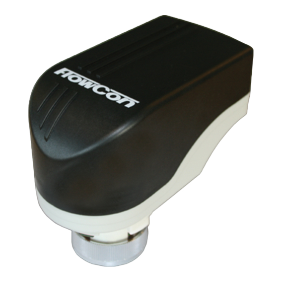
FlowCon FN.1.4 actuator
INSTALLATION AND OPERATION INSTRUCTION
The actuator type FlowCon FN.1.4 is an elec-
trical actuator supplied with a valve adaptor for
easy installation.
Figure 1
Fitting and
orientation of the actuator
Separate valve adaptor from actuator (figure 2)
by pressing the green release button and
turning the top part of the actuator 30° counter
clockwise. Then remove the top part of the ac-
tuator from the valve adaptor.
Figure 2
Rotate the black knob on the valve adaptor
counter clockwise (figure 3) so that the valve
adaptor stem and the green indicators are in top
position. Mount the valve adaptor on the in-
sert (which must already be installed in the valve
body) and finger tighten the connection union.
Do not use additional tools.
Never install the valve adaptor in closed po-
sition as this may damage the insert.
FlowCon FN.1.4 actuator
Denmark
The piping network can now be tested if necessary
by manually adjusting the valve adaptor knob.
WARNING: Do not force the knob in either
direction and never adjust the black knob
on the valve adaptor with a higher torque
than 1 Nm.
Figure 3
Then place the actuator on the valve adaptor
and turn clockwise 30°, until a "click" is heard.
Please do not mount the actuator more than 90°
from vertical (figure 4).
Max 90º
Figure 4
Dubai
USA
- 1 -
ELECTRICAL ACTUATORS
Singapore
www.flowcon.com
1B95074 - 04/2016
FlowCon International assumes no responsibility
for mistakes, if any, in any printed material.
Max 90º
Advertisement
Table of Contents

Related Manuals for FlowCon FN.1.4


Summary of Contents for FlowCon FN.1.4
- Page 1 ELECTRICAL ACTUATORS INSTALLATION AND OPERATION INSTRUCTION FlowCon FN.1.4 actuator The actuator type FlowCon FN.1.4 is an elec- The piping network can now be tested if necessary trical actuator supplied with a valve adaptor for by manually adjusting the valve adaptor knob.
- Page 2 FlowCon FN.1.4 actuator ELECTRICAL ACTUATORS Actuator wiring Dip switch settings The wiring diagrams for FlowCon FN.1.4 is Lift the silicone cap on the back of the actuator to shown in figure 5-8. get access to the dip switches (figure 9).
- Page 3 IMPORTANT: FlowCon FN.1.4 actuator and FN.1.4 valve adaptor are not custom made as a pair from the supplier, which means that a FN.1.4 actuator can be used with any FN valve adaptor with green indicators. Using other models of valve adaptors may cause valve damage.
- Page 4 FlowCon FN.1.4 actuator ELECTRICAL ACTUATORS Denmark Dubai Singapore www.flowcon.com 1B95074 - 04/2016 FlowCon International assumes no responsibility - 4 - for mistakes, if any, in any printed material.
Need help?
Do you have a question about the FN.1.4 and is the answer not in the manual?
Questions and answers