Table of Contents
Advertisement
Quick Links
Power supply
Output signals
General Information
> 100 mm
Ø 4.5 mm
R 1 ‡ 18 mm
at encoder
Without load
0.2 V
0.85 V
( 0.5 V)
† 150 m
> 100 mm
> 200 mm
Noise sources
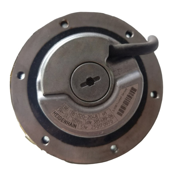
Reference mark for shaft/cap alignment
Mounting kit included
Spacer
Note: Mounting and commissioning is to be conducted by a qualified specialist under
compliance with local safety regulations.
In addition to this, the machine manufacturer or designer himself must define the other data
required for final assembly (e.g. anti-rotation lock for screws required or not) for the respective
application.
Do not engage or disengage any connections while under power.
The drive must not be put into operation during installation.
{
Mounting Instructions
*I_533392-01*
Advertisement
Table of Contents

Related Manuals for HEIDENHAIN ERN 1381.020


Summary of Contents for HEIDENHAIN ERN 1381.020
- Page 1 Power supply at encoder Without load Mounting Instructions Output signals Mounting kit included Spacer 0.2 V 0.85 V ( 0.5 V) General Information † 150 m > 100 mm > 100 mm > 200 mm Note: Mounting and commissioning is to be conducted by a qualified specialist under compliance with local safety regulations.
- Page 2 Assembly Electrical connection Do not remove threadlocker Press cable into place À Á Â Do not use the provided spacers for a coupling distance of 55±0.1 mm! Two ways of pressing the encoder out during dismounting Required mating dimensions À ¬...
Need help?
Do you have a question about the ERN 1381.020 and is the answer not in the manual?
Questions and answers