Table of Contents
Advertisement
Quick Links
Advertisement
Table of Contents

Related Manuals for HEIDENHAIN TNC 426CB


Summary of Contents for HEIDENHAIN TNC 426CB
- Page 1 Service Manual TNC 426 CB/PB TNC 430 CA/PA Kundendienst/Service...
- Page 2 * SERVICE MANUAL * TNC 426 CB/PB TNC 430 CA/PA Changes/Developments We are constantly working on technical improvements of our products. For this reason, details described in this manual may differ slightly from your control. In this case, please order a revised service manual from us. Duplication This manual is provided subject to the condition that no part of it shall be duplicated in any form without our prior consent.
- Page 3 Contents Service Manual TNC 426 CB/PB, TNC 430 CA/PA How to use this service manual Integrated monitoring system Minor error messages Bilinking error messages and their causes Hardware components TNC 426 B, TNC 430 A Logic unit LE TNC 426 CB, TNC 430 CA Connector designation and pin layouts Grounding diagram Block diagrams...
-
Page 4: Table Of Contents
Kundendienst/ Service Contents Page How to use this service manual ..................... 3 Integrated monitoring system ....................4 Minor error messages ......................5 Causes of minor error messages....................6 Blinking error messages and their causes................9 General error messages ......................10 PLC editor..........................13 Position encoder interface ......................20 Speed encoder interface......................20 Analogue axes ...........................21... - Page 5 Kundendienst/ Service Page Serial handwheels ........................115 15.1 Handwheel HR 130/330......................115 15.2 Handwheel HR 332........................117 15.3 Handwheel HR 410........................119 15.4 Error messages ........................121 3-D touch probes ........................122 16.1 Overview...........................122 16.2 Error messages ........................124 File management of TNC 426.B/430.A...................127 17.1 Structure of the hard disk......................127 17.2 TNC partition (TNC:\)........................128 17.3 PLC partition (PLC:\).........................130 17.4 Compiling the PLC program .....................132...
-
Page 6: How To Use This Service Manual
The Technical Manual is not enclosed with every control. In general, it is only supplied to the machine tool manufacturer and is updated by HEIDENHAIN, Traunreut. Therefore, it is absolutely necessary to contact the machine tool manufacturer, if errors occur that are due to a machine parameter or to the interface of the control. -
Page 7: Integrated Monitoring System
Kundendienst/ Service 2. Integrated Monitoring System TNC 426.B/430 features a comprehensive integral monitoring system to avoid input and operation errors, to locate errors and technical defects of the entire equipment (TNC, measuring systems, machine tool, cables etc.). The monitoring system is a fixed component of the TNC hardware and software; it is always active when the control is switched on. - Page 8 NC software 280 472/473. Further error messages are described in the Operating Manual (HEIDENHAIN) Technical Manual (HEIDENHAIN) CD-ROM TNC-GUIDE (HEIDENHAIN) The number in square brackets is the number of the error message in the error catalogue on CD-ROM.
-
Page 9: Minor Error Messages
Kundendienst/ Service Causes of minor error messages Operating parameters erased [947] • When the control is booted after power-on for the first time (new and exchange controls); When the control is booted for the first time after a software exchange; •... -
Page 10: Causes Of Minor Error Messages
Kundendienst/ Service Update the system data! [1845] During the power-on routine the control checks in the file SYS:\HDDVERS.A whether the current data (cycles, output templates, drive data etc.) are stored on harddisk. If this is not the case, the error message is output. - Page 11 Kundendienst/ Service MP: line w/o number [151] Machine parameter input error: A line was found without a machine parameter number (not an empty line or comment). MP: incorrect number [152] Machine parameter input error: The given machine parameter does not exist (incorrect number). MP: separator missing [153] Machine parameter input error:...
- Page 12 Error: 05:42:00 Please contact HEIDENHAIN, if an operating-system error message (white letters on black screen) is generated. The last operating-system error message is stored in ASCII format in the PLC partition in PLC:\ERROR.JOU. If a gross error occurs the control opens the contact "Control is Ready" which causes an emergency stop of the machine tool.
-
Page 13: Blinking Error Messages And Their Causes
CRC = Cyclic Redundancy Check (during data transfer) If one of these error messages comes up repeatedly, please contact HEIDENHAIN. Customized error messages by the machine tool manufacturer If the machine parameter MP 4020 bit 3 = 1, a PLC error message is displayed by the error markers M2924 to M3023 and M2815 in the PLC program. -
Page 14: General Error Messages
L No data request from hard disk although expected If the error message "FILE SYSTEM ERROR X" (X = identification letter, see above) comes up repeatedly, please note down the error message and the register contents and contact HEIDENHAIN. Ausgabe Blatt Service Manual TNC 426.B/430.A... - Page 15 2 = DSP If the error message "Processor check error XY" (XY = identification letters, see above) comes up repeatedly, please send the complete logic unit to HEIDENHAIN for repair. Please indicate the error message, the code letters and the register contents.
-
Page 16: Plc Editor
Kundendienst/ Service 4.2 PLC editor Blinking display Error cause The TNC cannot interpret the line as a PLC: invalid command PLC command (earlier versions: operand for jump is not [64] label) An unknown operand type was given. PLC: invalid operand type The command cannot be used for the given operand type. - Page 17 Kundendienst/ Service Blinking display Error cause An attempt was made to assign the result of a gated PLC: assignment in parentheses operand, although not all open parentheses had been [73] closed. PLC: too many parentheses Excessive nesting of parentheses [74] An attempt was made to nest more than 16 parenthetical expressions in each other.
- Page 18 Kundendienst/ Service Blinking display Error cause A logic operation was performed, but the result was PLC: logic assignment missing assigned to a new logic operation instead of to an [83] operand. A command was programmed that logically connects, PLC: word accumulator not loaded assigns or manipulates the loaded word accumulator, [84] although the word accumulator was not previously...
- Page 19 Kundendienst/ Service Blinking display Error cause Empty CASE instruction/KFIELD PLC: CASE/KFIELD is empty You programmed a CASE instruction followed immediately [92] by an ENDC instruction, or you programmed a KFIELD label immediately followed by an ENDK label. You programmed a command to logically connect, assign PLC: string accum.
- Page 20 Kundendienst/ Service Blinking display Error cause A label declared with EXTERN has not been PLC: external label not defined defined with GLOBAL in any of the associated [102] modules. A label declared with EXTERN has been inserted in PLC: external label in case the CM list of a CASE command.
- Page 21 Kundendienst/ Service Blinking display Error cause The processing of the program section to be executed PLC: time out cyclically took longer than 10 ms. Check the structure of [112] the subprogram for very calculation-intensive sections that you can start as SUBMIT jobs. The displayed processing time will be increased during RS232 data transfer and in handwheel mode.
- Page 22 Kundendienst/ Service Blinking display Error cause PLC error table PLC: error table not .PET The error table selected in OEM.SYS is not a .PET file. [1525] PLC error table PLC: error table not found The error table selected in OEM.SYS could not be found [1527] (file name or path name incorrect).
- Page 23 Kundendienst/ Service 4.3 Position encoder interface Blinking display Error cause Signal amplitude error; position encoder <Axis>encoder: amplitude too small [44] <Axis>encoder: frequency too high Signal frequency error; position encoder [45] <Axis> measuring system defective Error with distance-coded scale; position encoder [46] Ref mark <axis>: incorrect spacing During a reference-mark run on an encoder with distance-...
-
Page 24: Position Encoder Interface
Kundendienst/ Service 4.5 Analogue axes Blinking display Error cause Position monitoring (servo lag) Excessive servo lag in <axis> •Operation with velocity feedforward control: [38] Position monitoring exceeded; defined in machine parameter 1420.X. • Operation with servo lag: Servo lag monitoring exceeded; defined in machine parameter 1720.X. -
Page 25: Digital Axes
Kundendienst/ Service 4.6 Digital axes Blinking display Error cause Position monitoring (servo lag) Excessive servo lag in <axis> •Operation with velocity feedforward control: [38] Position monitoring exceeded; defined in machine parameter 1420.X. • Operation with servo lag: Servo lag monitoring exceeded; defined in machine parameter 1720.X. - Page 26 Kundendienst/ Service Blinking display Error cause Power stage for displayed axis too weak. Power stage in axis <axis> too weak [2188] U-Imax of the power stage for the displayed axis is Power stage <axis>: U-IMAX incorrect incorrect. [2192] U-IMAX = voltage of current sensor Imax of the power stage for the displayed axis is incorrect.
- Page 27 Kundendienst/ Service Blinking display Error cause The motor temperature has reached the maximum value. Motor temperature too high <axis> Information on the current motor temperature is fed to the control [1217] via the connectors X15 to X20 (speed encoder) as an analogue voltage at the pins Temperature +/- .
- Page 28 Time limit of rot. speed interrupt exceeded ; the last two places contain the time in [ms] (hex!) If the error message "DSP ERROR XXXX " is generate repeatedly, please contact HEIDENHAIN. Please indicate the error message, the code letter and the register contents.
- Page 29 4 secs. after power on. F2C8 9 Incorrect acknowledgement of command If the error message "DSP ERROR XXXX " is generate repeatedly, please contact HEIDENHAIN. Please indicate the error message, the code letter and the register contents. Ausgabe Blatt Service Manual TNC 426.B/430.A...
- Page 30 E200 Drive enabled E210 Drive disabled e.g. by EMERGENCY STOP If the error message "DSP ERROR XXXX " is generate repeatedly, please contact HEIDENHAIN. Please indicate the error message, the code letter and the register contents. Ausgabe Blatt Service Manual TNC 426.B/430.A...
- Page 31 Invalid PWM output selected (MP 2702) F1C0 Band filter parameter incorrect (MP 2540/2550) If the error message "DSP ERROR XXXX " is generate repeatedly, please contact HEIDENHAIN. Please indicate the error message, the code letter and the register contents. Ausgabe Blatt Service Manual TNC 426.B/430.A...
- Page 32 F2C0 Actual motor current above limit value F2D0 Status error PWM component If the error message "DSP ERROR XXXX " is generate repeatedly, please contact HEIDENHAIN. Please indicate the error message, the code letter and the register contents. Ausgabe Blatt Service Manual TNC 426.B/430.A...
-
Page 33: Hardware Components Of Tnc 426.B/430.A
Kundendienst/ Service 5. Hardware Components of TNC 426.B/430.A TNC component TNC 426 .B TNC 430.A LOGIC UNIT LE 426CB/PB 1) 2) Id.No. XXX XXX -- LOGIC UNIT LE 430CA/PA 1) 2) Id.No. XXX XXX -- VISUAL DISPLAY UNIT BC 110B (CRT interface) Id.No. -
Page 34: Logic Unit Le 426Cb/430Ca
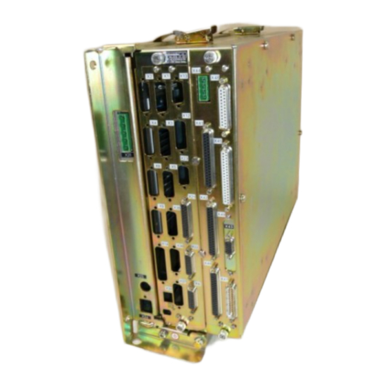
Kundendienst/ Service 6. LOGIC UNIT LE 426 CB/430 CA 6.1 Designation of the logic unit LE 426 CB/430 CA ID plate and program label of the logic unit ID plate of the processor board ID plate of the PLC graphics board is located on the board Ausgabe Blatt... -
Page 35: Logic Unit Le 426Pb/430Pa
Kundendienst/ Service Designation of the logic unit LE 426 PB/430 PA ID plate of the ID plate of the ID plate and program label processor board drive-control board of the logic unit ID plate of PLC graphics board is located on the board Ausgabe Blatt Service Manual TNC 426.B/430.A... -
Page 36: Hardware Components Of The Logic Unit Le 426.B/430.A
Kundendienst/ Service Hardware components of the logic unit LE 426.B/430.A Components overview LE 426 CB/430 CA 426 CB/CF 430 CA/CE Component PROCESSOR board PLC GRAPHICS board DRIVE (complete) Components overview LE 426 PB/430 PA 426 PB/PF 430 PA/PE Component PROCESSOR board PLC GRAPHICS board DRIVE (complete) DRIVE-CONTROL board... -
Page 37: Connector Designations And Pin Layouts
Kundendienst/ Service Connector Designations and Pin Layouts Connectors on the logic unit LE 426.B/430.A 7.1.1 Connector designation, logic unit LE 426 CB/PB LE 426 CB/CF NC power- Processor supply board graphics board Processor board X1 = position encoder axis 1 X2 = position encoder axis 2 X3 = position encoder axis 3 X4 = position encoder axis 4... - Page 38 Kundendienst/ Service LE 426 PB/PF NC power Processor Drive- supply board graphics control board board Processor board = position encoder axis 1 = position encoder axis 2 = position encoder axis 3 = position encoder axis 4 = position encoder axis 5 = position encoder axis 6 = nominal value outputs 1 - 6 = nominal value outputs 7 - 13...
- Page 39 Kundendienst/ Service LE 430 CA/CE NC power- Processor supply board graphics board Processor board = position encoder axis 1 = position encoder axis 2 = position encoder axis 3 = position encoder axis 4 = position encoder axis 5 = position encoder axis 6 = analogue outputs 1 - 6 = analogue outputs 7 - 13 X12 = touch probe (triggering) for...
- Page 40 Kundendienst/ Service LE 430 PA/PE NC power Processor Drive- supply board graphics control board board Processor board = position encoder axis 1 = position encoder axis 2 = position encoder axis 3 = position encoder axis 4 = position encoder axis 5 = position encoder axis 6 = nominal value outputs 1 - 6 = nominal value outputs 7 - 13...
- Page 41 Kundendienst/ Service 7.1.3 Pin layout of the NC POWER SUPPLY of LE 426 .B/430.A X31 NC power supply Terminal strip (pluggable) 5-pin Assignment LE 426PA LE 426CA Grounding conductor (ye/gr) Phase 1 330 V∼ to 450 V∼ via 140 V∼ to 450 V∼ via Phase 2 isolating transformer;...
- Page 42 Kundendienst/ Service Encoder (1 V Connector Id.No. Max. input frequency LE 426 PB 311 999 .., 312 000 .., 313 526 .., 313 527 .., 315 475 .., 350 kHz 317 349 .., 318 177 .., 318 178 .., 326 414 .., 326 416 .., 326 420 .., 326 421 ..
- Page 43 Kundendienst/ Service Logic unit LE 426CB Id.No. 312 007 .. Id.No. 313 528 .. Maximum input frequency: 350 kHz Square-wave input (TTL) Interpolation in TNC: 4-fold Maximum current consumption: 200 mA Flange socket with male insert (15-pin, D-Sub) Logic Unit Encoder Cable D-Sub connector Assignment...
- Page 44 Kundendienst/ Service X8 Analogue outputs 1 to 6 Flange socket with female insert (15-pin) Logic Unit Connecting Cable D-Sub Assignment D-Sub Color connector connector (female) 15-pin (male) 15-pin brown analogue output 1: ±10 V brown green do not assign yellow analogue output 2: ±10 V blue analogue output 5: ±10 V...
- Page 45 Kundendienst/ Service X12 Touch trigger probe for workpiece calibration Flange socket with female insert (15-pin) Logic Unit D-Sub connector Assignment (female) 15-pin 0 V (internal shield) standby start +15 V ± 10 % (U +5 V ± 5 % (U battery warning 0 V (U trigger signal...
- Page 46 Kundendienst/ Service X13 Touch trigger probe for workpiece calibration Flange socket with female insert (9-pin) Logic Unit D-Sub connector Assignment (female) 9-pin standby 0 V (U +15 V ± 5% (U +5 V ± 5% (U trigger signal trigger signal 3, 5, 6 do not assign Chassis...
- Page 47 Kundendienst/ Service X14 Measuring touch probe (option) Flange socket with female insert (25-pin) Logic Unit (adapter kit AK Id.No. 296 839 Connecting cable A-1016-6640 RENISHAW Id.No. 311 647 51) RENISHAW SP 2/1 D-Sub Assignment D-Sub Flange Connector connector connector socket on (male) (female) (male)
- Page 48 Kundendienst/ Service X22 V.11/RS-422 data interface Flange socket with female insert (15-pin) Logic Unit Connecting cable Id.No. 289 208 .. AB Id.No. 311 086 01 D-Sub Assignment D-Sub D-Sub D-Sub D-Sub connector connector connector connector connector (female) (male) (female) (male) (female) 15-pin 15-pin...
- Page 49 Kundendienst/ Service X25 Ethernet interface, RJ45 connector Maximum transfer rate: 200 kbaud to 1 Mbaud Maximum cable length: non-shielded: 100 m shielded: 400 m RJ45 connector Assignment (female) 8-pin TX– REC+ do not assign do not assign REC– do not assign do not assign The interface complies with the recommendations in IEC 742 EN 50 178 for separation from line power...
- Page 50 Kundendienst/ Service X41 PLC output Flange socket with female insert (37-pin, D-Sub) Logic Unit Connecting cable Id.No. 244 005 .. / Id.No. 263 954 .. D-Sub connector Assignment D-Sub connector (female) 37-pin (male) 37-pin Powered via X44, pin 3; can be switched off by EMERG. STOP grey/red brown/black white/black...
- Page 51 Kundendienst/ Service X42 PLC input Flange socket with female insert (37-pin, D-Sub) Logic Unit Connecting cable Id.No. 244 005 .., Id.No. 263 954 .. D-Sub connector Assignment D-Sub connector (female) 37-pin (male) 37-pin grey/red brown/black white/black I3 Acknowledgement ”control is ready ” green/black brown/red white/red...
- Page 52 Kundendienst/ Service X45 TNC operating panel (TE) Flange socket with female insert (37-pin, D-Sub) Logic Unit Connecting cable Id.No. 263 954 .. TE 401 D-Sub connector Assignment D-Sub D-Sub connector X2 D-Sub (female) 37-pin connector (female) 37-pin connector (male) (male) 37-pin 37-pin grey/red brown/black...
- Page 53 Kundendienst/ Service X43 Visual display unit (BC 110B at logic unit with 2-row connector) Flange socket with female insert (15-pin, D-Sub) Logic Unit Connecting cable Id.No. 250 477 .. BC 110 B Id.No. xxx xxx 3x D-Sub connector Assignment D-Sub D-Sub X1 D-Sub (female) 15-pin...
- Page 54 Kundendienst/ Service X43 Visual display unit (BC 120 at logic unit with 2-row connector Logic Unit Adapter Extension cable Id.No. 312 878 .. BC 120 Id.No. xxx xxx 3x 313 434 02 D-Sub Assignment 2-row / 3-row D-Sub D-Sub D-Sub connector connector connector...
- Page 55 Kundendienst/ Service X49 Visual display unit (BF 120) Logic Unit Extension cable Id.No. 312 876 .. Connecting cable Id.No. 312 875 .. BF 120 D-Sub Assignment D-Sub D-Sub D-Sub D-Sub D-Sub connector connector connector connector connector connector (female) (male) (female) (male) (female) (male)
- Page 56 Kundendienst/ Service Logic Unit Extension cable Id.No. 312 876 .. Connecting cable Id.No. 312 875 .. BF 120 D-Sub Assignment D-Sub D-Sub D-Sub D-Sub D-Sub connector connector connector connector connector connector (female) (male) (female) (male) (female) (male) 62-pin 62-pin 62-pin 62-pin 62-pin 62-pin...
- Page 57 Kundendienst/ Service X46 Machine operating panel Flange socket with female insert (37-pin, D-Sub) Logic Unit Connecting cable Id.No. 263 954 .. MB 420 D-Sub Assignment D-Sub D-Sub D-Sub connector connector connector connector (male) (female) 37-pin (male) 37-pin (female) 37-pin 37-pin I128 grey/red X–...
- Page 58 Kundendienst/ Service X47 PLC expansion interface 5 V interface Flange socket with male insert (25-pin, D-Sub) Logic Unit Connecting cable Id.No. 289 111 .. 1. PL 410 B D-Sub Assignment D-Sub D-Sub X1 D-Sub Assignment connector connector connector connector (male) 25- (female) (male) (female)
- Page 59 Kundendienst/ Service X48 PLC analogue input Flange socket with female insert (25-pin) D-Sub Assignment connector (female) 25-pin + constant current for Pt 100 – constant current for Pt 100 + measuring input for Pt 100 – measuring input for Pt 100 + constant current for Pt 100 –...
- Page 60 Kundendienst/ Service 7.1.6 Pin layouts at the drive-control board of LE 426.B/430.A X15 to X20, X60 Speed encoder (1 V Maximum input frequency: X15 to X20, X60 350 kHz X60 as of NC software 280 472 01 410 kHz Voltage interface 1 Vpp Flange socket with male insert (25-pin) Logic Unit AK Id.No.
- Page 61 Kundendienst/ Service X51 to X56, X61 Output to motor power stage (TNC 426 PB, TNC 430 PA only) Logic Unit Connecting Cable Id.No. 289 208 .. Expansion Card Id.No. 291 070 01 D-Sub connector Assignment D-Sub D-Sub X1, X2 (female) 15-pin connector connector D-Sub connector...
- Page 62 Kundendienst/ Service Logic units up to Id.No. xxx xxx 3x X50 Feed-rate enable Terminal Assignment + 24 V– do not assign Logic units as of Id.No. xxx xxx 4x X50 Feed-rate enable Terminal Assignment + 24 V– 2 to 6 do not assign Ausgabe Blatt...
-
Page 63: Connectors On The Plc I/O Boards
Kundendienst/ Service Connectors on the PLC I/O boards 7.2.1 Connectors on PL 405B Ausgabe Blatt Service Manual TNC 426.B/430.A Issue Page Connector designations and pin layouts 01.10.97... - Page 64 Kundendienst/ Service 7.2.2 Pin layout at PL 405B X1 Connection to LE or to 1st PL Logic unit Connecting Cable Id.No. 289 111 .. 1. PL 410 B D-Sub Assignment D-Sub D-Sub X1 D-Sub Assignment connector connector connector connector (male) (female) (male) 25- (female)
- Page 65 Kundendienst/ Service X2 Connection to 2nd PL 1. PL 410 B CONNECTING CABLE Id.No. 289 111 .. 2. PL 410 B X2 D-Sub Assignment D-Sub D-Sub X1 D-Sub Assignment connector connector connector connector (male) (female) (male) (female) 25-pin 25-pin 25-pin 25-pin brown, yellow, pink, red, violet red/blue, brown/green,...
- Page 66 Kundendienst/ Service PLC input on PL 410 B Assignment Assignment 1. PL 2. PL 3. PL 4. PL 1. PL 2. PL 3. PL 4. PL I192 I256 I320 I208 I272 I336 I193 I257 I321 I209 I273 I337 I194 I258 I322 I210 I274...
- Page 67 Kundendienst/ Service 7.2.3 Connectors on PL 410B Ausgabe Blatt Service Manual TNC 426.B/430.A Issue Page Connector designations and pin layouts 01.10.97...
- Page 68 Kundendienst/ Service 7.2.4 Pin layout at PL 410B X1 Connection to LE or to 1st PL Logic unit Connecting cable Id.No. 289 111 .. 1. PL 410 B D-Sub Assignment D-Sub D-Sub X1 D-Sub Assignment connector connector connector connector (male) (female) (male) (female)
- Page 69 Kundendienst/ Service X2 Connection to 2nd PL 1. PL 410 B Connecting cable Id.No. 289 111 .. 2. PL 410 B X2 D-Sub Assignment D-Sub D-Sub X1 D-Sub Assignment connector connector connector connector (male) (female) (male) (female) 25-pin 25-pin 25-pin 25-pin brown, yellow, pink, red, violet red/blue, brown/green,...
- Page 70 Kundendienst/ Service Assignment Assignment 1. PL 2. PL 3. PL 4. PL 1. PL 2. PL 3. PL 4. PL I192 I256 I320 I208 I272 I336 I193 I257 I321 I209 I273 I337 I194 I258 I322 I210 I274 I338 I195 I259 I323 I211 I275...
- Page 71 Kundendienst/ Service Assignment Assignment 1. PL 2. PL 3. PL 4. PL 1. PL 2. PL 3. Pl 4. PL O128 O160 O144 O176 O129 O161 O145 O177 O130 O162 O146 O178 O131 O163 O147 O179 O132 O164 O148 O180 O133 O165 O149...
-
Page 72: Connectors On The Keyboard Units
Kundendienst/ Service Connectors on the keyboard units 7.3.1 Connectors on TE 401B/420 Ausgabe Blatt Service Manual TNC 426.B/430.A Issue Page Connector designations and pin layouts 01.10.97... - Page 73 Kundendienst/ Service 7.3.2 Pin layout at TE 401B/420 X1 Connection of the soft keys of the X2 Connection to the logic unit (LE) visual display unit Plug-type connector with female insert (9-pin) Flange socket with male insert (37-pin) Pin no. Assignment Pin no.
-
Page 74: Connectors On The Visual Display Unit
Kundendienst/ Service Connectors on the visual display unit 7.4.1 Visual display unit BC 110 B X1 Connection to the logic unit X2 Connection of the soft keys to the Flange socket with male insert keyboard unit 2-row, 15-pin, SUB-D Flange socket with male insert (9-pin) Pin no. - Page 75 Kundendienst/ Service 7.4.2 Visual display unit BC 120 Connection to the logic unit X2 Connection of the soft keys to the Flange socket with male insert logic unit 3-row, 15-pin, D-SUB Flange socket with male insert 2-row, 9-pin, D-SUB Pin no. Assignment Pin layout: see logic unit X43 RL15...
- Page 76 Kundendienst/ Service 7.4.3 Visual display unit BF 120 X2 Connection to the logic unit X3 Connection of the soft keys to the Flange socket with male insert (62-pin) keyboard unit Flange socket with male insert (9-pin) Pin layout: see LE X49 Pin no.
-
Page 77: Connectors On The Interface Board
Kundendienst/Service 7.5 Connectors on the interface board X1 and X2 Connection of motor power stage (X51 to X56) of LE 426.B/430.A X351 SIMODRIVE device bus NB = not ready Monitoring of Uz, temperature (power stage), supply voltage and pulse enable IF = pulse enable Contact 1 of normally closed contact... -
Page 78: Connectors On The Machine Operating Panel Mb 420
Kundendienst/ Service Connectors on machine operating panel MB 420 Flange socket with female insert (37-pin, D-SUB) Logic Unit Connecting Cable Id.No. 263 954 .. MB 420 D-Sub connector Assignment D-Sub D-Sub connector D-Sub connector (female) 37-pin connector (female) 37-pin (male) 37-pin (male) 37-pin I128 grey/red... -
Page 79: Grounding Diagram
Kundendienst/ Service Ausgabe Blatt Service Manual TNC 426.B/430.A Issue Page Grounding diagram 01.10.97... -
Page 80: Block Diagrams
Kundendienst/ Service Ausgabe Blatt Service Manual TNC 426.B/430.A Issue Page Block diagrams 01.10.97... -
Page 81: Block Diagram Of Control Loop
Kundendienst/ Service Block diagram of control loop Block diagram of an analogue axis Block diagram of a digital axis Ausgabe Blatt Service Manual TNC 426.B/430.A Issue Page Block diagrams 01.10.97... -
Page 82: Detailed Block Diagram Of Digital Axis
Kundendienst/ Service Ausgabe Blatt Service Manual TNC 426.B/430.A Issue Page Block diagrams 01.10.97... -
Page 83: Board Description
Kundendienst/ Service 10. Board Descriptions LE 426 CB/430 CA LE 426 PB/430 PA Processor board Processor board • Interface • Interface Data interface V.24/RS-232-C Data interface V.24/RS-232-C Data interface V.11/RS-422 Data interface V.11/RS-422 Serial handwheel Serial handwheel Position encoder inputs Position encoder inputs 3-D touch probes 3-D touch probes... -
Page 84: Power Supply
Kundendienst/ Service Power Supply 11.1 Requirements to the external power supply 11.1.1 NC power supply (dc-link power supply) LE 426 CB, LE 430 CA: For LE 426CA an NC power supply of 140 V∼ to 450 V∼ at the terminals U1 and U2 is required. The monitoring of the supply voltage can be switched off via module 9167. - Page 85 Kundendienst/ Service 11.1.2 PLC power supply The PLC of the LE and the PL are operated with a control voltage of 24V- of the machine tool, generated according to IEC 742 EN 50 178 (basic insulation). Superimposed AC voltage components arising from a non-controlled three-phase bridge connection with a ripple factor of 5% (see German standard DIN 40110/10.75, section 1.2) are permissible.
- Page 86 Kundendienst/ Service Notes Service Manual TNC 426.B/430.A Ausgabe Blatt Issue Page Power supply 01.10.97...
- Page 87 Kundendienst/ Service 11.1.3 Power supply of the visual display unit BC 110B X1 = connection of logic unit X2 = connection of keyboard unit (for soft keys) X3 = Power connection Line voltage 110 V~ 220 V~ Voltage range 85 ... 132 V~ 170 ...
- Page 88 Kundendienst/ Service BC 120 BC 120 Line voltage 100 V to 240 V Frequency range 50 Hz to 60 Hz Power consumption 80 W Line connection with Euro connector Terminal Assignment black L1 ( blue MP ( yellow grey GND ( Ausgabe Blatt Service Manual TNC 426.B/430.A...
- Page 89 Kundendienst/ Service BF 120 BF 120 X1 Power supply Terminal Assignment +24V- power supply with basic insulation according to IEC 742, EN 50 178 Current consumption: 15 W Ausgabe Blatt Service Manual TNC 426.B/430.A Issue Page Power supply 01.10.97...
-
Page 90: Power Supply Of The Nc Part (Dc-Link Power Supply)
– dc-link power + 1) other voltage ranges on request Power consumption: approx.55 W Danger of electrical shock! The dc-link power supply may only be opened by HEIDENHAIN service staff. dc-link power supply Ausgabe Blatt Service Manual TNC 426.B/430.A Issue... - Page 91 re/bl (+ 5V*1) LH14 + 5V (0V*1) re/bk LH12 X3/1 +U_fan + 15V (+ 15V) LH13 + 12V (+ 12V) LH10 + 12V X4/2 F4 2A (0V) control X4/3 logic X3/2 0V_fan (- 12V) LH11 - 12V (- 15V) - 15V + 6,4V (+ 6,4V) wh/re...
-
Page 92: Checking The Power Supply Of The Nc Part (Dc-Link Power Supply)
If the measured values deviate distinctly from the values in the table, the power supply assembly is defective. Danger of electrical shock! The dc-link power supply may only be opened by HEIDENHAIN service staff. Fig. 1: The protective PCB is equipped with 4A/500V fuses. -
Page 93: Power Supply Of The Plc Part
Kundendienst/ Service 11.4 Power supply of the PLC X44 PLC power supply at the LE Terminal Assignment PLC outputs +24 V cannot be switched off O24 to O30 by EMERG. STOP Control is ready +24 V can be switched off O16 to O23 by EMERG. - Page 94 Kundendienst/ Service 11.4.1 Block diagram of PLC power supply Machine operating panel PLC input for testing only F1 F 2,0A +24V_PLC PLC output F3 F 2A +24V_PLC1 F2 F 3,15A +24V_PLC2 0 V *2 (0V PLC) for testing only +5V*2 Power supply for optocouplers of PL interface metallically insulated 0V*2...
-
Page 95: Buffer Battery
Kundendienst/ Service 11.5 Buffer battery The buffer battery is the power source for the RAM when the machine is switched off. If the error message Exchange buffer battery is displayed, the batteries must be exchanged within one week. The buffer batteries are located behind a screw fitting in the power supply unit of the LE. -
Page 96: Info Menu
Kundendienst/ Service 11.6 Info Menu Press key Function TNC in operating mode PROGRAMMING AND EDITING Prepare TNC for input of code number Enter code number, confirm with ENT The following information is displayed on the screen: Ö Charge of buffer battery Ö... -
Page 97: Keyboard Unit Te 401B/420
Kundendienst/ Service 12. Keyboard Unit TE 401B/420 12.1 Overview TE 401B Id.No. 250 517 05 (black) TE 420 Id.No. 313 038 01 (grey) Ausgabe Blatt Service Manual TNC 426.B/430.A Issue Page Keryboard unit TE 401/411 01.10.97... -
Page 98: Checking The Keyboard Unit
Kundendienst/ Service 12.2 Checking the keyboard unit The keyboard units can be checked quickly and reliably by means of a test adapter. 12.2.1 Checking the key functions Proceeding: Observe the safety instructions! • Switch off power. • Disconnect the keyboard unit from the LE and connect the test adapter (see section 21) to the keyboard unit. The key contacts can now be measured at the test adapter using an ohmmeter. - Page 99 Kundendienst/ Service 12.2.3 Key matrix of the keyboard unit X2 Pin 17 18 19 28 29 31 32 21 22 23 24 25 26 27 16 17 18 19 20 21 22 SL0 & " Ausgabe Blatt Service Manual TNC 426.B/430.A Issue Page Keryboard unit TE 401/411...
- Page 100 Kundendienst/ Service X2 Pin 17 18 19 28 29 31 32 21 22 23 24 25 26 27 16 17 18 19 20 21 22 SL0 SPACE Ausgabe Blatt Service Manual TNC 426.B/430.A Issue Page Keryboard unit TE 401/411 01.10.97...
- Page 101 Kundendienst/ Service X2 Pin 17 18 19 28 29 31 32 21 22 23 24 25 26 27 16 17 18 19 20 21 22 SL0 SPACE CALC HELP APPR Ausgabe Blatt Service Manual TNC 426.B/430.A Issue Page Keryboard unit TE 401/411 01.10.97...
- Page 102 Kundendienst/ Service X2 Pin 17 18 19 28 29 31 32 21 22 23 24 25 26 27 16 17 18 19 20 21 22 SL0 TOUCH PROBE CYCL CYCL CALL CALL STOP TOOL TOOL CALL CALL Ausgabe Blatt Service Manual TNC 426.B/430.A Issue Page Keryboard unit TE 401/411...
- Page 103 Kundendienst/ Service X2 Pin 17 18 19 28 29 31 32 21 22 23 24 25 26 27 16 17 18 19 20 21 22 SL0 GOTO Ausgabe Blatt Service Manual TNC 426.B/430.A Issue Page Keryboard unit TE 401/411 01.10.97...
- Page 104 Kundendienst/ Service 12.2.4 Key matrix of the VDU keys BC 110B X1 Pin 1) X2 Pin 1) Key 2) RL12 RL13 RL14 RL15 connector on the keyboard unit key on VDU X1: connection of ribbon cable VDU Ö keyboard unit (plug-type connector) X2: connection of cable keyboard unit Ö...
- Page 105 Kundendienst/ Service BC 120 / BF 120 X1 Pin 1) X2 Pin 1) Key 2) RL12 RL13 RL14 RL15 connector on the keyboard unit key on VDU X1: connection of ribbon cable VDU Ö keyboard unit (plug-type connector) X2: connection of cable keyboard unit Ö logic unit (D-SUB, 37-pin) SK = soft key ( SK1...SK8 from left to right) Ausgabe Blatt...
- Page 106 Kundendienst/ Service 12.2.5 Checking the potentiometers Proceeding: Observe the safety instructions! Connect the test adapter to X45 of the logic unit. Now the wiper voltages of the potentiometers can be measured with a multimeter. Potentiometer Voltage range Override F% 37 = 0V / 35 = + pot (0 ...
- Page 107 Kundendienst/ Service 12.2.7 Machine operating panel MB 420 The PLC inputs of the machine operating panel MB 420 (I128 - I150) can be checked at the 37-pin flange socket of MB 420 or at the flange socket X46 (connection of machine operating panel) of the TNC. For this purpose the TABLE function (see section 21.3) in the PLC mode is helpful as well.
-
Page 108: Visual Display Units
Kundendienst/ Service 13. Visual Display Units 13.1 Checking the visual display unit BC 110B If the screen remains dark when the machine is switched on, first check the power supply (line voltage) of the VDU. If the voltage supply is functioning properly, a square highlighted filed can be generated on the screen of the VDU (which must be switched on) by pressing the external test button on the back side of the unit. -
Page 109: Checking The Visual Display Unit Bc 120
Kundendienst/ Service 13.2 Checking the visual display unit BC 120 If the screen remains dark when the machine is switched on, first check the power supply (line voltage) at the Euro connector of the VDU. Power connector The control signals for the VDU can only be checked by means of an oscilloscope. The diagrams on the following page have been recorded with the VDU connected. - Page 110 Kundendienst/ Service Diagrams V-SYNC PIN 9 H-SYNC PIN 10 2V/DIV 2V/DIV 10 ms/DIV 20 µs/DIV R-analog PIN 7 1) Y-analog PIN 14 1) 0.2V/DIV 0.2V/DIV 5 ms/DIV 5 ms/DIV B-analog PIN 15 1) 0.2V/DIV 5 ms/DIV If measuring the color signals directly at the output of the logic unit (without the VISUAL DISPLAY UNIT connected), the amplitudes are about twice as large.
-
Page 111: Checking The Visual Display Unit Bf 120
Kundendienst/ Service 13.3 Checking the visual display unit BF 120 If the screen remains dark when the machine is switched on, first check the power supply (line voltage) at the 2-pin connector of the VDU. If the power supply is in order, the flat-panel display cannot be checked further without special testing equipment. BF 120 X1 Power supply Terminal... -
Page 112: Encoder Interface
Kundendienst/ Service 14. Encoder Interface 14.1 Position encoder circuit Position encoder inputs on the processor board of the logic unit X1 = Position encoder 1st axis X2 = Position encoder 2nd axis X3 = Position encoder 3rd axis X4 = Position encoder 4th axis X5 = Position encoder 5th axis X6 = Position encoder 6th axis X35 = Position encoder 7th axis (option) - Page 113 Kundendienst/ Service Locating an error in the position encoder circuit To find out whether the encoder or the encoder input of the logic unit is defective, the encoders can be switched at the logic unit. For this purpose the values of the related machine parameters must be changed, too. IMPORTANT: The allocation of the axes (1st axis, 2nd axis etc.) to the axis names (X, Y, Z etc.) is defined by the machine tool builder in the machine parameter MP 100.x (see machine parameter list).
- Page 114 Kundendienst/ Service Flowchart to locate an error in the position encoder circuit X encoder: amplitude too small The following machine parameter configuration serves as an example: MP 100.x = -----CZYX ( X = 1. axis, Y = 2. axis, Z = 3. axis, C = 4. axis) MP 110.0 = 1 (X axis at position input X1) MP 110.1 = 2 (Y axis at position input X2) MP 110.2 = 3 (Z axis at position input X3)
-
Page 115: Speed Encoder Circuit
Kundendienst/ Service 14.2 Speed encoder circuit Digital axes normally are operated with two encoders per axis. In most cases sealed encoders are used as position encoders. The speed encoder is a rotary encoder incorporated in the servo drive. IMPORTANT: The allocation of the axes (1st axis, 2nd axis etc.) to the axis names (X, Y, Z etc.) is defined by the machine tool builder in the machine parameter MP 100.x (see machine parameter list). - Page 116 Kundendienst/ Service Flowchart to locate an error in the speed encoder circuit X motor encoder: amplitude too small The following machine parameter configuration serves as an example: MP 100.x = -----CZYX ( X = 1st axis, Y = 2nd axis, Z = 3rd axis, C = 4th axis) X-axis at speed encoder input X15 Y-axis at speed encoder input X16 Z-axis at speed encoder input X17...
-
Page 117: Electrical Inspection Of An Encoder
Kundendienst/ Service 14.3 Electrical inspection of an encoder In order to give a precise statement on the electrical function of an encoder, it must be measured with a phase angle measuring unit (PWM), an oscilloscope and a leak tester. (see operating instructions of encoder diagnostic set) Several adapters have been created to measure the different types of encoder signals (11µA, 1Vpp, TTL) at TNC 426.B/430.A with the PWM. - Page 118 Kundendienst/ Service Notes Ausgabe Blatt Service Manual TNC 426.B/430.A Issue Page Encoders 01.10.97...
-
Page 119: Serial Handwheels
Kundendienst/ Service 15. Serial Handwheels Several handwheels can be operated as options TNC 426.B/430.A. These handwheels must be adapted in the machine parameters MP7640 to MP7671.X. 15.1 Handwheel HR 130/330 HR 130 Id.No. 254 040 -- HR 330 Adapter connector for HR 330 HR 130.001 Id.No. - Page 120 Kundendienst/ Service 15.1.2 Checking the keys of the handwheel HR 330 Depending on machine parameter MP 7640 the HR 330 handwheel behaves as follows: MP7640 = 1: HR 330 (all keys evaluated by NC) By pressing the axis buttons on the operating panel the cursor can be moved to Actual value transfer or Datum setting.
-
Page 121: Handwheel Hr 332
Kundendienst/ Service 15.2 Handwheel HR 332 HR 332 Connecting Adapter connector (12-pin → 9-pin) cable Permissive Signal buttons of EMERG. STOP handwheel EMERG. STOP Permissive button 1) Permissive button 1) Connecting Permissive button 1) terminals for not assigned EMERG.STOP shield + 12V Signal + 12V... - Page 122 Kundendienst/ Service 15.2.2 Checking the keys of the handwheel HR 332 MP7640 = 4: HR 332 By pressing the axis buttons on the operating panel the cursor can be moved to Actual value transfer or Datum setting. The axis keys on the handwheel serve to move the handwheel symbol on the screen. In MP7645.0 can be defined, whether all twelve keys and the corresponding LEDs can be addressed by PLC or whether the axis buttons and their LEDs are excepted.
- Page 123 Kundendienst/ Service 15.3 Handwheel HR 410 Connecting terminals for EMERG.STOP Permissive buttons of handwheel Signal Common permissive button Permissive button 2 Permissive button 1 Emerg. stop 1 Emerg. stop 1 Emerg. stop 2 Emerg. stop 2 + 12V External shield + internal shield = housing Signal + 12V...
- Page 124 Kundendienst/ Service 15.3.1 Checking data transfer of the handwheel HR 410 The serial handwheel HR 410 can be checked by means of an oscilloscope. The following signals can be measured at the handwheel input X23 of the logic unit. They must correspond to the diagrams below: 2V/DIV Pin 6 Pin 8...
-
Page 125: Error Messages
Kundendienst/ Service 15.4 Error Messages Handwheel not ready [1096] Check handwheel connections Handwheel ? X [63] : No peripheral unit connected : Code of peripheral unit does not match MP7640 C Y : Contamination (Y = axis) : Transmission error during receipt : Received BCC check sum incorrect : Peripheral unit has recognized wrong code : Peripheral unit has recognized wrong BCC check sum... -
Page 126: D Touch Probes
Kundendienst/ Service 3-D Touch Probes 16.1 Overview 16.1.1 Touch probes for calibration and setup of workpieces TS 220 with connecting cable 16.1.2 Touch probes for digitizing workpieces TS 120 Adapter connector for TS 120 Ausgabe Blatt Service Manual TNC426.B/430.A Issue Page 3-D touch probes 01.10.97... - Page 127 Kundendienst/ Service Notes Ausgabe Blatt Service Manual TNC426.B/430.A Issue Page 3-D touch probes 01.10.97...
-
Page 128: Error Messages
Kundendienst/ Service 16.2 Error Messages 16.2.1 Error messages in the probing mode Touch point inaccessible [50] • After starting a probing function no touch point was reached within the traverse defined in machine parameter MP6130 Stylus already in contact [52] •... - Page 129 Kundendienst/ Service 16.2.2 Error messages when digitizing 3-D contours Wrong axis programmed [331] • The probe axis in the scanning cycle RANGE is not identical with the calibrated touch probe axis. Faulty range data [444] • In the RANGE scanning cycle a MIN coordinate is larger than or equal to the corresponding MAX value. •...
- Page 130 Kundendienst/ Service Plane wrongly defined [313] • One of the coordinates of the starting point in the cycle CONTOUR LINES is identical with the touch probe axis. Start position incorrect [445] • The starting point coordinate that is identical to the starting axis is outside the range. Axis double programmed [307] •...
-
Page 131: File Management Of Tnc 426.B/430.A
To view the PLC partition, the code number 807667 must be entered. SYS: 128 Mbytes for files related to the system (system files, NC dialogues, HEIDENHAIN cycles etc.) The SYS is not visible and cannot be selected! Caution: If you change the SYS partition, your system may not correctly work any more. -
Page 132: Tnc Partition (Tnc:\)
Kundendienst/ Service 17.2 TNC partition (TNC:\) 17.2.1 Calling the TNC partition Press key Function TNC in operating mode PROGRAMMING/EDITING Call program management The structure of the directory is displayed on the left half of the screen. Press the arrow keys to jump to the subdirectories. - Page 133 Kundendienst/ Service 17.2.2 Overview of the files in the TNC partition The following files are stored in the TNC partition: File type Extension TNC NC program, HEIDENHAIN dialogue Active tool table TOOL.T NC program, DIN/ISO Pallet table Datum table Text file (ASCII) Pocket table TOOL_P.TCH...
-
Page 134: Plc Partition (Plc:\)
Kundendienst/ Service 17.3 PLC partition (PLC:\) 17.3.1 Calling the PLC partition Press key Function TNC in operating mode PROGRAMMING AND EDITING Prepare TNC for input of code number Enter code number, confirm with ENT After entering the code number the PLC menu is displayed. If the words READ ONLY appear at the lower left of the screen, the machine tool builder has protected the PLC partition by an additional code number. - Page 135 Kundendienst/ Service 17.3.2 Overview of the files in the PLC partition The following files are stored in the PLC partition: File type Extension TNC PLC programs .PLC Text files (ASCII) Texts for help files .HLP Important system file OEM.SYS Other system files .SYS Data for axis error compensation .COM...
-
Page 136: Compiling The Plc Program
Kundendienst/ Service 17.4 Compiling the PLC program Loading a file into the EDITOR: Press key Function Call program management Select and call desired file Now the file is in the PLC editor; it can be activated any time by pressing the soft key Loading <NAME.PLC>... -
Page 137: Calling The Plc Error Table (X.pet) For Diagnosis
Kundendienst/ Service 17.5 Calling the PLC error table (<Name>.PET) for diagnosis Press key Function Operating mode PROGRAMMING AND EDITING Prepare TNC for input of code number Enter code number, confirm with ENT Call program management Press the error keys to select the PLC error table displayed as PLC:\ <Name>.PET in the PLC menu;... -
Page 138: Generating A Cross-Reference List For Diagnosis
Kundendienst/ Service 17.6 Generating a cross-reference list for diagnosis Press key Function Operating mode PROGRAMMING AND EDITING Prepare TNC for input of code number Enter code number, confirm with ENT Call program management Press the arrow keys to move the cursor to the PLC program to be converted Switch soft-key row Press soft key... -
Page 139: Calling The Active Machine Parameter List
Kundendienst/ Service 17.7 Calling the active machine parameter list Press key Function TNC in operating mode PROGRAMMING AND EDITING Prepare TNC for input of code number Enter code number, confirm with ENT The active machine parameter list is displayed on the screen. The TNC automatically enters this parameter list in OEM.SYS as MPFILE = xxxx. -
Page 140: Data Interfaces
For data transfer the TNC 426.B/430.A can be switched to the following 5 interface operating modes: FE 1: For connection of the HEIDENHAIN floppy disk unit FE 401 B (or FE 401 from software 230 626 03) or other peripheral units. - Page 141 Kundendienst/ Service 18.1.1 Interface configuration and allocation of operating modes In the operating modes PROGRAMMING AND EDITING and TEST RUN the setup for the data interfaces is called by pressing and the soft key On the left half of the screen the RS-232-C interface is configured, on the right half the RS-422-C. On the lower left of the screen the operating modes PROGRAMMING/EDITING, PROGRAM RUN and TEST RUN can be allocated to either RS-232-C or RS-422-C.
-
Page 142: Machine Parameters For The Data Interfaces
Kundendienst/ Service By pressing the arrow keys GOTO you can select the desired settings (operating mode, baud rate and interface assignment) and set them according to your requirements with the key. To exit the MOD function RS 232/RS 422 SETUP, press the soft key 18.2 Machine parameters for the data interfaces In the operating modes FE 1, FE 2 and LSV/2 the interface parameters cannot be changed. -
Page 143: Error Messages
Kundendienst/ Service 18.3 Error Messages 18.3.1 Error messages at the TNC in the FE mode In this operating mode, the floppy disk unit outputs errors in the following format: (SOH) ERR: (SP) (SP) (SP) [XXX] (ETB) (BCC) XXX = error number The following errors may be displayed: Input/Output Errors ERR: 001 = wrong command code... - Page 144 Kundendienst/ Service 18.3.2 Error messages during data transfer Data transfer erroneous [189] X = A Faulty character frame Parity error The control has received the character for "Negative Acknowledgement" (NAK) more than 3 times The control has transmitted the character for "Negative Acknowledgement" (NAK) more than 3 times Baud rate not possible [197]...
-
Page 145: Wiring Diagram Of The Data Interfaces
Wiring diagrams of the data interfaces 18.4.1 V.24/RS-232-C data interface with RS-232-C adapter block (full wiring) If the pin layout of your peripheral unit differs from the above layout, the HEIDENHAIN connecting cable may not be used. 18.4.2 V.24/RS-232-C data interface with RS-232C adapter block (simplified wiring) - Page 146 Kundendienst/ Service 18.4.3 V.11/RS-422 data interface The RS-422-/V.11 data interface has identical pin layouts at the logic unit X22 and at the RS-422 adapter block. Ausgabe Blatt Service Manual TNC 426.B/430.A Issue Page Data interfaces 01.10.97...
-
Page 147: Data Input And Output
The functions described in this sections are valid for the FE1 interface mode. If you want to use these functions in connection with a personal computer, the HEIDENHAIN data transfer software TNC.EXE is required. After having called the program management in the operating mode PROGRAMMING AND EDITING the drives are displayed: RS 232:\ Ö... -
Page 148: File Overview Tnc 426.B/430.A
Depending on the partition (TNC:\, PLC:\) in which the data transfer menu is activated, only certain file types are offered to be transferred. The following data may be stored on the harddisk: File type Extension in TNC TNC:\ partition NC program HEIDENHAIN dialogue TOOL.T Active tool table NC program DIN/ISO Pallet table Datum table Text file (ASCII) TOOL_P.TCH... - Page 149 Kundendienst/ Service 19.3.1 Output of files with the extension .H, TOOL.T, .I, .P, .D, .A, TOOL_P.TCH Press key Function Operating mode PROGRAMMING/EDITING Call program management Select the screen structure such that the TNC is displays file names on the left and on the right side. On the left half of the screen select the directory from which you want to copy files to the external data medium.
- Page 150 Kundendienst/ Service 19.3.2 Output of the machine parameter list <NAME>.MP Press key Function TNC in operating mode PROGRAMMING/EDITING Prepare TNC for input of code number Enter code number, confirm with ENT Call program management Select the screen structure such that the TNC is displays file names on the left and on the right side.
- Page 151 Kundendienst/ Service 19.3.3 Output of files with the extension .PLC, .A, .HLP, .SYS, .COM, .CMA, .PET Press key Function Operating mode PROGRAMMING/EDITING Prepare TNC for input of code number. Enter code number, confirm with ENT. Call program management. Select the screen structure such that the TNC is displays file names on the left and on the right side.
-
Page 152: Data Input
Kundendienst/ Service 19.4 Data input Note: The following flowcharts for input and output of individual files only apply for the data transfer software TNCremo, the operating mode LSV2 File Server . If you use a different data transfer software, the procedure may differ from this description. - Page 153 Kundendienst/ Service 19.4.1 Input of files with the extension H, TOOL.T, .I, .P, .D, .A, TOOL_P.TCH Press key Function TNC in operating mode PROGRAMMING/EDITING Call program management. Select the screen structure such that the TNC is displays file names on the left and on the right side. On the left half of the screen select the directory to which you want to copy files from the external data medium.
- Page 154 Kundendienst/ Service 19.4.2 Input of the machine parameter list <NAME>.MP Press key Function TNC in operating mode PROGRAMMING/EDITING Prepare TNC for input of code number. Enter code number, confirm with ENT. Call program manager. Select the screen structure such that the TNC is displays file names on the left and on the right side.
- Page 155 Kundendienst/ Service 19.4.3 Input of files with the extension .PLC, .A, .HLP, .SYS, .COM, .CMA, .PET Press key Function TNC in operating mode PROGRAMMING/EDITING Prepare TNC for input of code number. Enter code number, confirm with ENT. Call program management. Select the screen structure such that the TNC is displays file names on the left and on the right side.
-
Page 156: Interface To The Servo Amplifier
Kundendienst/ Service 20. Interface to the Servo Amplifier 20.1 Nominal value output to servo amplifier (analogue/digital) IMPORTANT: The allocation of the axes (1st axis, 2nd axis etc.) to the axis names (X, Y, Z etc.) is defined by the machine tool builder in the machine parameter MP 100.X (see machine parameter list). -
Page 157: Analogue Speed Nominal Value Interface At Connector X8/X9
Kundendienst/ Service 20.2 Analogue speed nominal value interface at connector X8/X9 20.2.1 Specifications of the analogue outputs Load capacity: > 5 kΩ Lmin < 2 nF Lmax Short-circuit stability: Outputs permanently short-circuit proof +10V ± 100 mV Voltage range: amax −10V ±... - Page 158 Kundendienst/ Service 20.2.2 Checking the analogue speed nominal value interface Proportionally to the traverse speed the control outputs an analogue voltage between 0V and ±10V 1). The easiest way to determine this voltage is to measure with the TEST ADAPTER directly at the LOGIC UNIT or with a multi- meter at the terminals of the servo amplifier.
- Page 159 Kundendienst/ Service Measuring setup to check the analogue speed nominal value interface logic unit servo amplifier X8/X9 ANALOGUE test adapter multimeter 5.15V Observe the safety instructions! Ausgabe Blatt Service Manual TNC 426.B/430.A Issue Page Interface to the servo amplifier 01.10.97...
-
Page 160: Digital Interface To The Servo Amplifier, Connectors X51 - X56/X61
Kundendienst/ Service 20.3 Digital interface to the servo amplifier, connectors X51 - X56/X61 20.3.1 Checking the digital speed nominal value interface A digital servo amplifier can only be tested with a DCG (= Drive Control Generator; see section Test Units). Proceeding to check a PWM axis (TNC 426.B/430.A): Preparations at the machine tool: •... - Page 161 Kundendienst/ Service Notes Ausgabe Blatt Service Manual TNC 426.B/430.A Issue Page Interface to the servo amplifier 01.10.97...
-
Page 162: Switching Over The Position Display For Servicing
Kundendienst/ Service 20.4 Switching over the position display for servicing Press key Function TNC in MACHINE operating mode (manual, full sequence etc.) Activate MOD function Select dialogue POSITION DISPLAY if necessary Switch to the desired position display: NOML: nominal position DIST: distance to go ACTL:... -
Page 163: Adjustment Of The Feed Rate At The Servo Amplifier
Kundendienst/ Service 20.5 Adjustment of the feed rate at the servo amplifier 20.5.1 Analogue axes Check and adjust the machine parameters. (If you alter a machine parameter, note down the original value and re-enter it after finishing the inspection.) Entry value Function Original entry value velocity feedforward control... -
Page 164: Offset Adjustment
Kundendienst/ Service 20.6 Offset adjustment 20.6.1 Analogue axes a) Offset adjustment with code number Press key Function TNC in operating mode PROGRAMMING AND EDITING Prepare TNC for input of code number Enter code number for offset adjustment; confirm with ENT On the screen the contents of the offset memory are now displayed in converter steps (1 conv. - Page 165 Kundendienst/ Service b) Cyclic offset adjustment via machine parameter In the machine parameter MP1220 the cycle time [1s] is defined after which an offset is compensated by one converter step. To switch off the automatic offset adjustment, enter the value 0 in the machine parameter MP1220. Caution! If an offset voltage of 100 mV is reached with automatic offset adjustment, the control switches off, generating the error message...
-
Page 166: Integrated Oscilloscope
Kundendienst/ Service 20.7 Integrated oscilloscope TNC 426.B/430.A features an integrated oscilloscope. To activate the OSCILLOSCOPE mode, enter the code number 688 379. With this oscilloscope you can record and store the characteristic curves of the axes in up to 4 channels: ACTL SPEED Actual feed rate of the axis [mm/min];... - Page 167 Kundendienst/ Service The recorded data are stored until you start a new recording operation or activate another graphic function. The colors for the oscilloscope are configured in MP7356.x. After entering the code number, the setup menu is displayed: Select the desired position by pressing the cursor keys and then set the parameters. OUTPUT You may choose whether the nominal speed is output as a jump or as a ramp.
- Page 168 Kundendienst/ Service Press the OSCI soft key to call the Oscilloscope display: During recording, the trains of selected signals are constantly depicted. After terminating the recording, the memory contents is displayed. In addition, the signal type and the resolution are displayed for each channel. The length of the recorded range referenced to the entire memory contents is displayed as a bar in the status field.
- Page 169 Kundendienst/ Service Explanation of the soft keys: When you select one of the four channels a soft-key row is displayed consisting of the following keys: The signal is inverted. Arrows Shift the signal upwards or downwards. Increase vertical resolution. Decrease vertical resolution. Optimum vertical resolution.
-
Page 170: Plc Interface
Kundendienst/ Service PLC Interface 21.1 Specifications PLC inputs Voltage ranges Logic Unit PL 410 B "1" signal: U 13 V to 30.2 V "0“ signal: U – 20 V to 3.2 V Current ranges "1" signal: I 3.8 mA to 8.9 mA 2.5 mA to 6 mA "0"... -
Page 171: Checking The Plc Inputs And Outputs
Kundendienst/ Service 21.2 Checking the PLC inputs and outputs The test unit (see section 21) can be used to check the PLC inputs and outputs on the logic unit (X41, X42, X46). The voltage level of the PLC inputs and the output current of the PLC outputs on the PL 405B/410B can be measured directly at the terminals. - Page 172 Kundendienst/ Service PLC outputs The PLC outputs can be checked as follows: • Connect the test unit between LE and PLC (measure directly at the PL boards). Press key Function TNC in operating mode PROGRAMMING AND EDITING Prepare TNC for input of code number Enter code number, confirm with ENT Call TABLE function Table of the outputs is displayed...
- Page 173 Kundendienst/ Service Measuring setup for the PLC inputs and outputs on the LE Logic unit Interface Test adapter Multimeter 5.15V X41 : PLC output X42 : PLC input X46 : machine operating panel Observe the safety instructions! Ausgabe Blatt Service Manual TNC 426.B/430.A Issue Page PLC interface...
-
Page 174: Diagnosis In The Plc Mode
Kundendienst/ Service 21.3 Diagnosis in the PLC mode 21.3.1 TRACE mode Activation via soft key The TRACE mode provides the possibility of controlling the logic states of the markers, inputs, outputs, timers and counters; it also serves to check the contents of bytes, words and double words of the compiled PLC program. - Page 175 Kundendienst/ Service 21.3.2 LOGIC diagram The logic states of up to 16 operands (M, I, O, T, C) can be displayed simultaneously on the screen. 1024 PLC scans can be traced. Activation of the logic diagram: Press key Function Press soft key Press soft key Note: By pressing the soft key...
- Page 176 Kundendienst/ Service Selecting the operands and start of tracing Press key Function A table is displayed from which the operands can be selected. The control requests the positions of the table in a dialogue. Wrong inputs can be cleared by pressing DEL. It is possible to enter a trigger condition for each operand.
- Page 177 Kundendienst/ Service 21.3.3 TABLE function Press key Function Activation of the TABLE function Key on VDU After pressing a soft key, the corresponding table is activated. The logic states of the markers, inputs, outputs, counters and timers are dynamically displayed. In the tables for bytes, words and double words, the display can be switched between HEX and DECIMAL.
-
Page 178: Output "Control Is Ready" And Acknowledgement For Test "Control Is Ready
Kundendienst/ Service 21.4 Output "Control is ready" and acknowledgement for test " Control is ready " Important functions are monitored by the TNC 426.B/430.A by way of a self-diagnosis system (electronic assemblies such as micro-processor, EPROM, RAM, positioning systems, encoders etc.). For the EMERGENCY STOP routine a PLC input (X42/4) and a PLC output ("Control is ready") are available on the control. - Page 179 If an error occurs, the output "Control is ready" must generate an EMERGENCY STOP. Since this function is of great importance, the control checks this output each time when the power is switched on. HEIDENHAIN recommends the following wiring: Ausgabe Blatt Service Manual TNC 426.B/430.A...
- Page 180 If an error occurs, the output "Control is ready" must generate an EMERGENCY STOP. Since this function is of great importance, the control checks this output each time when the power is switched on. The wiring recommended by HEIDENHAIN can be seen from the wiring diagram. The external electronics has to match the preset conditions.
- Page 181 Kundendienst/ Service TNC 426 flowchart X41/34 X42/4 Screen display Waiting for control voltage Relay ext. DC voltage missing Recognition of control voltage at X42/4 and switching off the signal "Control is ready“ at X41/34 by main processor (t < 66 ms). Maximum time in which the acknowledgement "Control is ready“...
- Page 182 Kundendienst/ Service TNC 430 flowchart X41/34 X42/4 8 14 Screen display Waiting for control voltage Relay ext. DC voltage missing Recognition of control voltage at X42/4 and switching off the signal "Control is ready“ at X41/34 by main processor (t < 66 ms). Maximum time in which the acknowledgement "Control is ready“...
-
Page 183: Non-Volatile Plc Markers And Words
Kundendienst/ Service 21.5 Non-volatile PLC markers and words 21.5.1 Data backup on hard disk To save certain states of the PLC program, the non-volatile PLC memory range can be backed up on hard disk and reloaded for testing. Press key Function TNC in operating mode PROGRAMMING AND EDITING Prepare TNC for input of code number... - Page 184 Kundendienst/ Service 21.5.2 Playing back data into RAM Press key Function TNC in operating mode PROGRAMMING AND EDITING Prepare TNC for input of code number Enter code number; confirm with ENT Call TABLE function Switch soft-key row File: PLC\PLCMEM.A Enter destination path and file name under which the states of the PLC markers and words are backed up on harddisk.
-
Page 185: Tests Units
Kundendienst/ Service 22. Test Units 22.1 Universal Measuring Adapter Used: • Universal test unit for D-Sub connectors, 9pin to 37pin (Id.No. 255 480 01) MESSADAPTER MEASURING ADAPTER 1 2 3 4 5 6 7 8 9 The measuring adapter can be used to test the inputs and outputs of D-Sub connectors (9-pin to 37-pin). On the following page the adapter cables are shown that are required for the different connectors Ausgabe Blatt... - Page 186 Kundendienst/ Service Adapter cable, 9-pin Id.No. 255 481 01 Adapter cable, 15-pin Id.No. 255 482 01 Adapter cable, 25-pin Id.No. 255 483 01 Adapter cable, 37-pin Id.No. 255 484 01 Ausgabe Blatt Service Manual TNC 426.B/430.A Issue Page Test units 01.10.97...
-
Page 187: Encoder Diagnostic Set
Kundendienst/ Service 22.2 Encoder Diagnostic Set Used: • to test the electrical functions of an encoder • Id.No. 254 599 0; further information please see from the operating instructions of the Diagnostic Set. • Adapter block TNC 426.B/430.A - PWM8 see next page Ausgabe Blatt Service Manual TNC 426.B/430.A... - Page 188 LS / LB oder Meßsystem 1Vss 15pol. (Lage) Encoder 1Vpp 15pin (position) Meßsystem 1Vss Stecker, Adapter- Kabel, Adapter- Encoder 1Vpp Adapter connector Adapter connector ohne Z1-Spur 15/12pol. Id.-Nr. 310 199 02 Id.-Nr. 324 555 01 2,0m PWM 8 1Vss LS / LB oder Meßsystem TTL 15pol.
-
Page 189: Drive Control Generator (Dcg)
Kundendienst/ Service 22.3 Drive control generator (DCG) Used: • To drive inverters with PWM signals Id.No. 296 737 01 Accessories: • Adapter cable for connection to PWM interface, 15-pin., D-SUB: Id.No. 295 720 01 • Adapter cable for connection to PWM interface, 16/34-pin, plug-type connector: Id.No. - Page 190 Kundendienst/ Service Description of controls and displays: Err.1 If the drive does not send a STANDBY signal when the switch is in UP position (active), the DCG is not switched on and the axis cannot be moved. By setting the toggle switch to DOWN position (off), the STANDBY signal is not evaluated and the axis can be moved.
- Page 191 Considerable damage and personal injury may result from improper use. HEIDENHAIN is not liable for any damage or personal injury caused directly or indirectly or by improper use or incorrect operation.
-
Page 192: Exchange Instructions
23.1 Important notes Observe the safety instructions! 23.1.1 Required equipment PC with HEIDENHAIN data transfer software TNCBACK.EXE 1 IC-extraction and insertion tool (for exchanging NC software and boards) 1 MOS protection device (only required for exchanging boards or EPROMs) 23.1.2 MOS protection When the EPROMs are to be exchanged, a MOS protection is definitely required, since otherwise EPROMs may be destroyed. -
Page 193: Exchanging The Nc Software Pgm No. 280 470 - 473
NC software, the machine tool model and features, some items may by skipped. Basically all files stored on the hard disk should be backed up on an external data medium. For this purpose HEIDENHAIN offers the data transfer software TNCBACK.EXE free of charge (see section 23.3). - Page 194 Kundendienst/ Service Notes Ausgabe Blatt Service Manual TNC 426.B/430.A Issue Page Exchange instructions 01.10.97...
- Page 195 Kundendienst/ Service 23.2.3 Converting data on the hard disk from binary format to ASCII format Before the EPROMs on the processor board of TNC 426.B/430.A can be exchanged, the data on the hard disk must be converted from binary into ASCII format. A minimum free memory of 1.5 times the largest file on the hard disk is required.
- Page 196 Kundendienst/ Service 23.2.4 Exchanging EPROMs • Switch off the machine and exchange the EPROMs using the IC-extraction tool. When exchanging the EPROMs, a MOS protection is definitely required, since otherwise MOS components on the board or the EPROMs may be destroyed. Caution! Avoid any unprotected handling or contact of the boards or EPROMs with statically charged objects (packaging material, storage etc.).
- Page 197 Kundendienst/ Service 23.2.5 Putting the control into service • Switch on power. • Confirm error messages with ⇒ see sec. 23.2.7 LANGUAGE LOAD ERROR XX Message ⇒ see sec. 23.2.7 UPDATE THE SYTEM DATA! Message ⇒ see sec. 3 Message POWER INTERRUPTED •...
- Page 198 Kundendienst/ Service 23.2.6 Converting the files on the hard disk from ASCII format to binary format After activating the machine parameters the ASCII files have to be reconverted into binary format. Binary files and the corresponding ASCII files are related as follows: ⇔...
- Page 199 English dialogue stored on the EPROM is automatically loaded. The other dialogues are provided by HEIDENHAIN on a floppy disk (in DOS format) together with a transfer program. They have to be installed on the hard disk of TNC 426.B/430.A.
- Page 200 Kundendienst/ Service 23.2.8 Re-establishing the original state of the machine tool • Enter code number 75368 to execute an offset adjustment (TNC 426.B/430.A only) • If touch probes are used, they should be recalibrated after the software exchange. • Machines with swivel head: Re-initialize the swivel head Information can be obtained from your machine tool builder •...
- Page 201 Kundendienst/ Service Notes Ausgabe Blatt Service Manual TNC 426.B/430.A Issue Page Exchange instructions 01.10.97...
-
Page 202: Backing Up Hard-Disk Data
The hard-disk data should be backed up regularly on an external data medium (PC). For this purpose HEIDENHAIN offers the data transfer software TNCBACK.EXE which is supplied with every service manual (disk in envelope). This program can also be ordered separately (Id.No. 280 534 --). -
Page 203: Exchanging The Logic Unit
Kundendienst/ Service 23.4 Exchanging the LOGIC UNIT 23.4.1 Preparations at the machine tool • Bring machine tool or axes into a defined state (see sec. 23.2.2) 23.4.2 Important information on the hard disk All part programs, tool tables, machine parameters, PLC programs, compensation value tables, NC dialogues in all languages etc. - Page 204 Kundendienst/ Service 23.4.3 Dismounting the LOGIC UNIT a) Switch power off b) Loosen all plug connections and clamped joints at the logic unit. Loosen ground terminal and central signal ground Note: If a PL is mounted at the upper side of the housing, D-Sub connector it must be removed before dismounting the logic unit! Loosen knurled screw...
- Page 205 Kundendienst/ Service c) Loosen the 4 mounting screws on the logic unit d) Remove the old logic unit and insert the new logic unit. 23.4.4 Mounting the LOGIC UNIT The logic unit is mounted in the reverse order that is was dismounted. a) Insert and secure the logic unit.
-
Page 206: Exchanging The Hard Disk
Kundendienst/ Service 23.5 Exchanging the hard disk Proceeding: • Back-up the hard-disk data (see sec. 23.3). • Switch power off. • Open the logic unit. • Disengage the plug connections œ and loosen the mounting screws of the hard disk. Remove the mounting screws Disconnect œ... -
Page 207: Machine Parameter List
Kundendienst/ Service 24. Machine Parameter List Ausgabe Blatt Service Manual TNC 426.B/430.A Issue Page Machinen parameter list 01.10.97...
Need help?
Do you have a question about the TNC 426CB and is the answer not in the manual?
Questions and answers