Advertisement
Quick Links
For mounting the scale drum, please see separate Mounting Instructions.
Für die Montage der Teilungstrommel bitte separate Anleitung beachten.
Pour le montage du tambour gradué, consulter les instructions séparées.
Per il montaggio del tamburo graduato attenersi alle istruzioni separate.
Para el montaje del tambor de graduación, por favor considerar las instrucciones separadas.
Mounting Instructions
Montageanleitung
Instructions de montage
Istruzioni di montaggio
Instrucciones de montaje
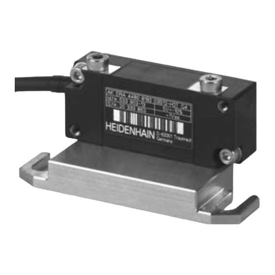
AK ERA 4x80
Scanning Head
Abtastkopf
Tête captrice
Testina di scansione
Cabezal captador
10/2019
Advertisement

Related Manuals for HEIDENHAIN AK ERA 4x80


Summary of Contents for HEIDENHAIN AK ERA 4x80
- Page 1 Mounting Instructions Montageanleitung Instructions de montage Istruzioni di montaggio Instrucciones de montaje AK ERA 4x80 Scanning Head For mounting the scale drum, please see separate Mounting Instructions. Für die Montage der Teilungstrommel bitte separate Anleitung beachten. Abtastkopf Pour le montage du tambour gradué, consulter les instructions séparées.
- Page 2 Contents Page Seite Inhalt Notes Hinweise Sommaire Warnings Warnhinweise Indice Items supplied Lieferumfang Mounting procedure Hinweise zur Montage Indice Dimensions Abmessungen 11 Mounting 11 Montage 14 Final steps 14 Abschließende Arbeiten 15 Adjustment and diagnosis 15 Justage und Diagnose Page Pagina Página Remarques...
- Page 3 Notes Hinweise Remarques Indicazioni Indicaciones The PWM 21 testing device and the ATS software are available for checking the mounting and adjusting the reference mark position. Um den Anbau zu überprüfen oder die Referenzmarkenlage abzugleichen, steht das PWM 21 und die ATS-Software zur Verfügung. Pour vérifier le montage, ou pour régler la position de la marque de référence, utiliser le PWM 21 et le logiciel ATS.
- Page 4 Warnings Warnhinweise Avertissements Avvertenze Advertencias Note: – Mounting and commissioning is to be conducted by a qualified specialist under compliance with local safety regulations. – Do not engage or disengage any connections while under power. – All mounting surfaces must be clean and free of burrs. –...
- Page 5 Attention : – Le montage et la mise en service doivent être assurés par un personnel qualifié dans le respect des consignes de sécurité locales. – Le connecteur ne doit être connecté ou déconnecté qu’hors potentiel. – Toutes les surfaces de montage doivent être propres et exemptes de bavures. –...
- Page 6 Items supplied Lieferumfang Contenu de la livraison Standard di formitura Suministro Montageanleitung Mounting Instructions Instructions de montage Istruzioni di montaggio AK ERA 4xx0 scanning head Instrucciones de montaje Abtastkopf AK ERA 4xx0 xxxxxxxxxxxxxxxxxxxxxxxxxxxxxxxxxxxxxxxxxxxx. AK ECA 4410 xxxxxxxxxxxxxxxxxxxxxxxxxxxxxxxxxxxx xxxxxxxxxxxxxxxxxxxxxxxxxxxxxxxxxxxxxxxxxxxxxxxxxxx xxxxxxxxxxxxxxxxxxxxxxxxxxxxxxxxxx AK ECA 4490 F, M xxxxxxxxxxxxxxxxxxxxxxxxxxxxxxxxxxxxxxxxxxxxxxxxxxxxxxxx 1/2015 Tête captrice AK ERA 4xx0...
- Page 7 Mounting procedure Hinweise zur Montage Procédure de montage Avvertenze per il montaggio Indicaciones para el montaje Make sure the drum outside diameter and the diameter indication on the mounting aid Information about the area of the outside diameter of the scale match! The information must match.
- Page 8 If necessary, clean the scale drum and the scanning head with a lint-free cloth and isopropyl alcohol. Bei Bedarf Teilungstrommel und Abtastkopf mit fusselfreiem Tuch und Isopropylalkohol reinigen. En cas de besoin, nettoyer le tambour gradué à l’aide d’un chiffon sans peluches et d’alcool isopropylique.
- Page 9 Dimensions Abmessungen Dimensions Dimensioni Dimensiones Bearing Lagerung Roulement Cuscinetto Rodamiento Cable support Kabelabstützung Support de câbles Supporto del cavo Apuntalamiento del cable Reference pulse track Referenzimpulsspur Piste de l’impulsion de référence Traccia impulso di riferimento Pista Impulso de referencia ...
- Page 10 Alternative mounting option ISO 4762 – M3x(a+4) – 8.8 Alternative Anbaumöglichkeit ISO 7092 – 3 – 500HV – 8.8 Possibilité de montage alternative Possibilità di montaggio alternativa 16.5 Posible montaje alternativo 3.4 0.2 Rz 16 76.75 49.38 52.13 0.1/20 A...
- Page 11 Mounting Montage Montage Montaggio Montaje Make sure the drum outside diameter and the diameter indication on the mounting aid match! Auf Übereinstimmung von Trommelaußendurchmesser und Durchmesserangabe auf der Montagehilfe achten! Veiller à ce que le diamètre extérieur du tambour corresponde bien au diamètre indiqué sur l’outil de montage ! Prestare attenzione alla corrispondenza tra diametro esterno del tamburo e indicazione del diametro sull’aiuto di montaggio! Tener en cuenta que en la ayuda para el montaje, el diámetro exterior del tambor y el valor indicado del...
- Page 12 Gently press the scanning head and mounting aid against the scale drum and the mounting surface and fasten with the screw. ISO 4762−M3x25−8.8 = 0.83±0.05 Nm Abtastkopf plus Montagehilfe mit geringer Kraft gegen die Teilungstrommel und Anschraubfläche drücken und festschrauben. Exercer une légère pression sur l’ensemble tête captrice/outil de montage pour les pousser vers le tambour gradué...
- Page 13 Alternative mounting option Alternative Anbaumöglichkeit ISO 4762−M3x16−8.8 Possibilité de montage alternative ISO 7092−3−200HV−8.8 Possibilità di montaggio alternativa Posible montaje alternativo = 0.83±0.05 Nm...
- Page 14 Final steps Abschließende Arbeiten Opérations finales Operazioni finali Trabajos finales Check the resistance between the connector housing and the machine. Desired value: 1 max. Elektrischen Widerstand zwischen Steckergehäuse und Maschine prüfen. Sollwert: 1 max. Vérifier la résistance électrique entre le carter de la prise et la machine. Valeur nominale: 1 ...
- Page 15 Adjustment and diagnosis Justage und Diagnose Réglage et diagnostic Taratura e diagnostica Ajuste y diagnóstico The PWT 101 testing device (documentation ID 1162581) as well as the PWM 21 testing device can be used to check the signals. The adjustment of the reference mark position can be performed by means of the PWM 21 testing device and the ERA 4xx0 mounting wizard. Please use the “ERA 4xx0 mounting wizard”...
- Page 16 Check the incremental signals Check the signal amplitude and adjust if necessary. The signal amplitude should lie within the green range (between 0.8 Vpp and 1.2 Vpp). The signal deviation should lie within the green range. If the specified adjustment values cannot be reached, check the mounting tolerances and inspect for contamination.
- Page 17 Check the reference mark position To check the reference marks, traverse the entire measuring range. RM.Pos. In the bar graphs, the drag indicators (black triangles) indicate the minimum and maximum value, respectively. The drag indicators must be within the green (good) or yellow (sufficient) areas.
- Page 18 Activate HSP Signal amplitudes must lie between 0.95 V and 1.05 V. HSP aktivieren Signalamplituden müssen zwischen 0,95 V und 1,05 V liegen. Activer le HSP Les amplitudes de signal doivent se trouver entre 0,95 V et 1,05 V. Attivare HSP Le ampiezze del segnale devono essere comprese tra 0,95 V e 1,05 V.
- Page 19 Status Display Funktionsanzeige Affi chage fonctionnel Visualizzazione della funzionalità Indicador de función The integrated function display permits both an assessment of the incremental signals as well as a check of the reference mark signal, and enables a fast functional check in the fi eld without technical aid. Die integrierte Funktionsanzeige erlaubt sowohl eine Beurteilung der Inkrementalsignale als auch eine Kontrolle des Referenzmarkensignals und ermöglicht eine schnelle Funktionskontrolle im Feld ohne Hilfsmittel.
- Page 20 DR. JOHANNES HEIDENHAIN GmbH Dr.-Johannes-Heidenhain-Straße 5 83301 Traunreut, Germany { +49 8669 31-0 | +49 8669 32-5061 E-mail: info@heidenhain.de Technical support | +49 8669 32-1000 Measuring systems { +49 8669 31-3104 E-mail: service.ms-support@heidenhain.de NC support { +49 8669 31-3101 E-mail: service.nc-support@heidenhain.de...
Need help?
Do you have a question about the AK ERA 4x80 and is the answer not in the manual?
Questions and answers