SystemAir SAVE VTC 300 Installation And Service
Hide thumbs
Also See for SAVE VTC 300:
- User manual (70 pages) ,
- Installation and service (47 pages) ,
- Replacement instructions manual (18 pages)

Related Manuals for SystemAir SAVE VTC 300


Summary of Contents for SystemAir SAVE VTC 300
- Page 1 SAVE VTC 300 Installation and Service Document in original language | 211464 · A001...
- Page 2 This also applies to products already ordered, as long as it does not affect the previously agreed specifications. Systemair is not liable or bound by the warranty if these instructions are not adhered to during installation or service. 211464 | A001...
-
Page 3: Table Of Contents
Contents Declaration of Conformity .........1 6.7.5 System Preferences..... 21 6.7.6 Service ....... 21 Disposal and recycling ........2 6.7.7 Help ........27 Warnings............2 Before starting the system ......28 Product information .........2 Service ............28 General ..........2 Warnings..........28 Installation recommendation regarding Internal Components...... -
Page 5: Declaration Of Conformity
Heat recovery ventilation unit: SAVE VTC 300 (The declaration applies only to product in the condition it was delivered in and installed in the facility in accordance with the included installation instructions. The insurance does not cover components that are added or actions carried out subsequently on the product). -
Page 6: Disposal And Recycling
• Make sure that filters are mounted before starting the unit. Product information General This installation manual concerns air handling unit type SAVE VTC 300 manufactured by Systemair. SAVE VTC 300 include the following model options: Right or Left models: R (Right), L (Left) (see figure 2). -
Page 7: Installation Recommendation Regarding Condensation
Transport and storage The SAVE VTC 300 should be stored and transported in such a way that it is protected against physical damage that can harm panels etc. It should be covered so dust, rain and snow cannot enter and damage the unit and its components. -
Page 8: Technical Data
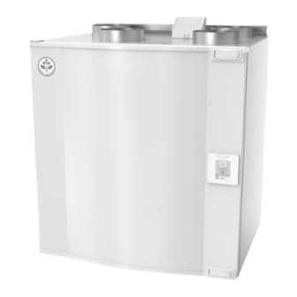
| Product information The appliance is delivered in one piece containing all necessary components, wrapped in plastic on a pallet for easy transportation. Technical Data 4.4.1 Dimensions and Weight Fig. 1 Dimensions of right hand unit * Inspection hatch. ** Drainage. The unit weight is 72 kg. -
Page 9: Power Consumption And Fuse Size
This section describes how to install the unit correctly. To ensure a proper and fail free operation it is important that the unit is installed according to these instructions. Unpacking Verify that all ordered equipment are delivered before starting the installation. Any discrepancies from the ordered equipment must be reported to the supplier of Systemair products. 211464 | A001... -
Page 10: Where/How To Install
| Installation Where/how to install SAVE VTC 300 are meant for indoor installation in a heated space. Mount the unit on a vertical flat surface. It’s impor- tant that the unit is completely levelled before it is put into operation. -
Page 11: Electrical Connections
Electrical Connections The SAVE VTC 300 is wired internally from factory. The electrical connection box can be found in the supply air fan com- partment. The top cover plate is removed by removing 2 screws in the lower front edge of the cover plate (figure 4). - Page 12 | Installation 5.3.2.1 Main board layout The SAVE VTC 300 is equipped with built-in regulation and internal wiring. The figure shows the main circuit board. See wiring diagram for more information. Fig. 5 Main circuit board connections Position Description Main circuit board...
-
Page 13: Savecair Control
SAVECair control | Position Description Analog output 1 — Rotor of the heat exchanger (VSR, VTR units) / Damper control (VTC units) Terminals for speed control of extract air fan Terminals for speed control of supply air fan 5.3.2.2 External connections (Connection board) External connections to the main circuit board are done via connection board situated outside of the unit. -
Page 14: Common Symbols
| SAVECair control If the start-up wizard is cancelled it will start again during next power up of the unit, this will continue until start-up wiz- ard is successfully finished. Common symbols The following selection symbols are common and are present in most menu pages: On and Off slider to activate or Back button to return to a previous deactivate a function. -
Page 15: Home Screen
SAVECair control | Home screen Touching home icon (pos. A) in drop- down menu list (pos. 1) will always returns you to home screen after commissioning. 1. Drop-down menu list 2. Active user mode 3. Airflow settings 4. Temperature settings 5. - Page 16 | SAVECair control Icon Text Description Sets speed of both supply and extract air fans to Low levels when user is away from home for a long period of time. HOLIDAY ECO mode is active. Delay in days. Sets speed of both supply and extract air fans to maximum High levels and temperature setpoint offset to –3 K when apartment is more crowded than usual.
-
Page 17: Temperature Settings
SAVECair control | 6.5.2 Temperature settings Temperature can be set at SET TEMPERATURE menu accessible from the home screen by touching TEMPERATURE icon with thermometer. Default temperature value is 18°C (range 12–30°C). Use up and down arrows or a slider to change the value. Then touch the SET to confirm changes. -
Page 18: Indoor Air Quality
| SAVECair control Important It is not recommended to set fan to Off in standard households. If manual fan stop is activated, the unit should be provided with dampers in exhaust and fresh air ducts to avoid cold draught and risk of condensation when the unit has been stopped. -
Page 19: Main Menu
SAVECair control | Icon Text Description Function prevents formation of the ice on the heat exchanger during cold Defrosting outdoor temperatures. Warm air from the living space is used to defrost the heat exchanger using a damper inside the outdoor air duct. The unit switches from outdoor air to Secondary air secondary air while the extract air fan stops and warm secondary air increases the temperature inside the heat exchanger. -
Page 20: Alarms
| SAVECair control 6.7.1.1 Components Type and settings of heat exchanger, heater, cooler, extra controller. 6.7.1.2 Sensors Values from sensors and load of fans (rpm). 6.7.1.3 Input Status Status of configured analog, digital and universal inputs. Connected component type and raw value (volts) is displayed. 6.7.1.4 Output Status Status of configured analog, digital and universal outputs. - Page 21 SAVECair control | Alarm name Explanation Do the following Indicates failure of pre-heater to Check the pre-heater reset button. Defrosting error preheat the incoming outdoor air (in Check the pre-heater cabling. case Extra controller is configured as Contact your installation company or place of purchase.
- Page 22 | SAVECair control Alarm name Explanation Do the following Rotor guard Indicates a rotor malfunction. If the rotating heat exchanger has No rotation guard signal for 180 stopped. Check the rotor belt. seconds. If the heat exchanger is still rotating, check that the quick connector for the sensor is connected and that there is an air gap of 5-10 mm...
-
Page 23: Week Schedule
SAVECair control | Alarm name Explanation Do the following Time for filter change. Change the filter. Filter Change filter according to the instructions in the User Manual. Details about filter retailers can be found in Help menu. Extra controller alarm Error from external device. -
Page 24: Filter
| SAVECair control 6.7.3.1 Schedule airflow settings Touch settings icon to go to SCHEDULE AIRFLOW SETTINGS menu. In this menu set airflow level for scheduled and unscheduled periods. Available levels: Off, Low, Normal, High or Demand. Set temperature setpoint offset for both periods (-10°C – 0°C). Demand level is available only if Demand Control or External fan function is active. -
Page 25: System Preferences
SAVECair control | 6.7.5 System Preferences Configuration of unit location, language and time. Change the following information: • Language (default language is English) • Country (default country is UK) • Unit address (address, post code) • Unit date and time, activate or deactivate summer/winter time switch. Time will automatically change between summertime and wintertime according to European standard, based on Greenwich time zone and set unit location. - Page 26 | SAVECair control 6.7.6.2 Output Configuration of outputs. Settings for analog, digital and universal output terminals on the main board and connection board, configuration of functionality. Fan output PWM (Pulse-width modulation) signal and triac output are already pre-addressed to specific terminals and cannot be changed, all other outputs are free for configuration by commissioning.
- Page 27 SAVECair control | • Set outdoor air temperature interlock. Default setting is 10°C. Range: 0–20°C. • Set actuator type. Default value is 0–10 V Range: 0–10 V / 2–10 V / 10–0 V / 10–2 V. • Set circulation pump stop delay. Default setting is 5 minutes. This option is available if Water / Change-over heat- er type is selected.
- Page 28 | SAVECair control Pressure Setting Flow (CAV) Manual External (VAV) Pa, inwc Airflow l/s, m /h, cfm measurement unit. P-Band 0–100% 0–3000 rpm 0–500 Pa 0–100% Default setting: 150 Pa I-time Off / 1–240 sec. Off / 1–240 sec. Off / 1–240 sec. Off / 1–240 sec.
- Page 29 SAVECair control | Set I-time, default setting is Off, Range: Off/1–120 sec. • Select airflow level for Improving Air Quality. Range: Normal / High / Max. • Select airflow level for Good Air Quality. Range: Low / Normal. RH Transfer Control Note: Setting is available if heat exchanger type is set as Rotating.
- Page 30 Fan speed differ for each household because of different unit size, duct system and system pressure. In order to find correct fan speed, external tool must be used at Systemair website. 1. Go to Systemair website and find your unit.
-
Page 31: Help
SAVECair control | • Shows communication information for HMI. Modbus device number (1–10) and Modbus termination: Active/ Inactive. 6.7.6.7 Logs Information about alarms, fans and parameters are stored in Logs menu. Fans Levels • Time counter for each supply air fan level duration is displayed. Counted and total time. Reset counted time. Level 1: 0% Level 2: 1–29% Level 3: 30–44%... -
Page 32: Before Starting The System
| Before starting the system • Alarms— detailed description of all alarms. • Troubleshooting— information about all different possible malfunctions. Before starting the system When the installation is finished, check that: • The unit is installed in accordance with the instructions •... -
Page 33: Internal Components
Service | Internal Components Fig. 10 Components Position Description Fan, supply air Fan, extract air Filter, outdoor air Filter, extract air Defrost damper Motor, defrost damper Cover plate, defrost damper Heat exchanger Condensation tray Condensation drain Connection box Cover plate, electrical connection box Print card with terminals Temperature sensor, supply air Temperature sensor, outdoor air... -
Page 34: Troubleshooting
Bypass Damper appears in the HMI. 8.2.1.4 Heat exchanger SAVE VTC 300 is equipped with a highly efficient, counter flow plate heat exchanger. Required supply air temperature is therefore normally maintained without adding additional heat. - Page 35 Service | Action Malfunction 1. Check the HMI for alarms. 2. Check that all fuses and fast couplings are connected (main power supply and fast Fans do not start couplings for supply and extract air fans). 3. Check that the week schedule is ON and running in AUTO mode. The week schedule might be in OFF mode with the air flow set to OFF (chapter 6.7.3).
-
Page 36: Accessories
| Accessories Accessories SAVE VTC 300 have many available accessories that can be used to expand functionality of the unit and increase com- fort level. Recommended accessories can be always found at Systemair website www.systemair.com by searching the article number or the name of the desired accessory. - Page 37 • 3 — Extract air • 4 — Exhaust air Component/product — Article number: • Systemair-1 CO2 duct sensor — 14906 • Systemair-E CO2 sensor — 14904 • Room sensor 0-50C (temperature) — 211525 • Systemair-E CO2 RH Temperature — 211522 Installation and connection 1.
-
Page 38: Temperature Control
| Accessories Temperature control 9.3.1 Electrical reheater Electrical reheater is used for supply air heating during cold outside temperatures. Electrical reheater should be installed inside of the unit. • ELH — Electrical heater • OHT — overheat protection sensor • 1 — Outdoor air •... - Page 39 Accessories | 2 Remove knobs in the reheater compartment (pos. 1), they will be used to hold the reheater in place. Remove the main circuit board cover plate by remov- ing 2 screws (pos. 2) in the lower front edge of the plate.
-
Page 40: Electrical Duct Pre-Heater
| Accessories 9.3.2 Electrical duct pre-heater Electrical pre-heater can be installed in the outdoor air duct to pre-heat outdoor air before it reaches the unit and pre- vent icing in the heat exchanger. • PH — electrical pre-heater • ECT — extra controller temperature sensor •... -
Page 41: Duct Water Heater
Accessories | 4. Configure connection of the pre-heater. Go to Service menu. Select Output menu. In next menu select DIGITAL tab. Select the digital output to which the pre-heater connected. Example if it is connected to DO3 on the connection board, then select DIGITAL OUTPUT 3 and select Step Controller Y4 Extra Controller from the output type list. -
Page 42: Duct Water Cooler
| Accessories Important Do NOT use 24V DC power output from the connection board for valve actuator. 2. Connect actuator (S) to any free analog output. 3. The frost protection sensor (FPT) should be strapped on a surface on the return water pipe. Connect FPT sensor to any free analog input. - Page 43 Accessories | • WC — water cooling battery • SAT — supply air temperature sensor • S — valve actuator • 1 — Outdoor air • 2 — Supply air • 3 — Extract air • 4 — Exhaust air Component/product —...
-
Page 44: Change-Over Coil (Dx)
| Accessories Configuration 1. Go to Service menu 2. Enter password (default 1111) 3. Activate the actuator. Go to Components menu, select Cooler menu and select type as Water. Choose actuator voltage type. Do advanced settings if necessary. 4. Configure connection of the duct cooler. Go to Service menu. Select Output menu. In next menu select ANALOG tab. -
Page 45: Airflow Control
Accessories | 2. Connect actuator (S) to any free analog output. 3. Connect the compressor or other device to any free digital output and 24V. 4. The frost protection sensor (FPT) should be strapped on a surface on the return water pipe. Connect FPT sensor to any free analog input. -
Page 46: Installation/Maintenance
| Accessories Note: The accessory package contains all needed parts for VAV conversion, however for use with CAV, an IRIS damper or a similar device with known K factor has to be purchased. Component/product — Article number: • VAV/CAV conversion kit SAVECair — 140777 •... -
Page 47: Filters
DIGITAL OUTPUT 3 and select signal type as Outdoor-/Exhaust Air Damper from the output type list. Filters The filters need to be replaced when polluted. New sets of filters, if possible, should be acquired directly from Systemair to meet filter quality standards. If that is not possible, please contact your installer or wholesaler. - Page 48 Systemair UAB Linų st. 101 LT–20174 Ukmergė, LITHUANIA Phone +370 340 60165 Fax +370 340 60166 www.systemair.com...
Need help?
Do you have a question about the SAVE VTC 300 and is the answer not in the manual?
Questions and answers