Advertisement
Quick Links
Room temperature controller with push-button interface 4-gang
Room temperature controller with push-button interface 4-gang
Art.-No.: 2178TS
Operationsmanual
1 Safety instructions
Electrical equipment may only be installed and fitted by electrically skilled persons.
Failure to observe the instructions may cause damage to the device and result in fire and
other hazards.
Danger of electric shock on the KNX installation. Do not connect any external voltage to
the inputs. Doing so may damage the device(s), and the SELV potential on the KNX bus
line will no longer be available.
These instructions are an integral part of the product, and must remain with the end
customer.
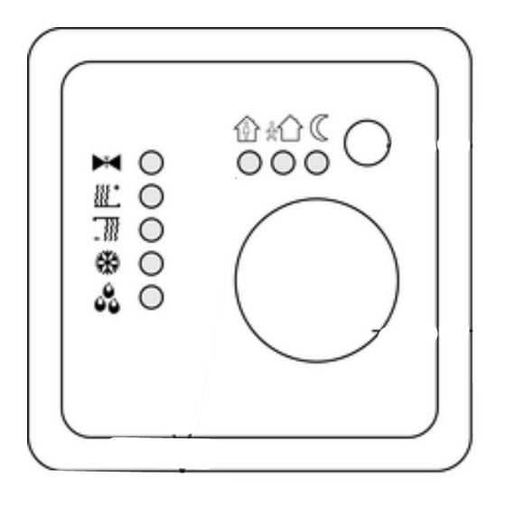
2 Device components
(1) Motion button
(2) Adjustment dial
(3) Status LED
3 Function
System information
This device is a product of the KNX system and complies with the KNX directives. Detailed
technical knowledge obtained in KNX training courses is a prerequisite to proper
understanding.
The function of this device depends upon the software. Detailed information on loadable
software and attainable functionality as well as the software itself can be obtained from the
manufacturer´s product database.
Planning, installation and commissioning of the device are carried out with the aid of KNX-
certified software. Full functionality with KNX commissioning software version ETS3.0d
onwards.
An updated version of the product database, technical descriptions and conversion programs
and other auxiliary programs are available on our Internet website.
32561923
J:0082561923
picture 1
1/7
03.08.2010
Advertisement

Related Manuals for Jung A2178TSSWM


Summary of Contents for Jung A2178TSSWM
- Page 1 Room temperature controller with push-button interface 4-gang Room temperature controller with push-button interface 4-gang Art.-No.: 2178TS Operationsmanual 1 Safety instructions Electrical equipment may only be installed and fitted by electrically skilled persons. Failure to observe the instructions may cause damage to the device and result in fire and other hazards.
-
Page 2: Operation
Room temperature controller with push-button interface 4-gang Intended use Single-room temperature control in KNX installations Load types: LED or electronic relay Installation in appliance box acc. to DIN 49073 Product characteristics Measurement of room temperature and comparison with setpoint temperature Setpoint specification by selection of the operating mode Operating modes Comfort, Standby, Night operation, Frost/heat protection Heating and cooling mode... - Page 3 Room temperature controller with push-button interface 4-gang Changing the room temperature Turn the adjustment dial in the clockwise direction. Setpoint temperature is increased. Turn the adjustment dial in the anti-clockwise direction Setpoint temperature is decreased. Activating comfort extension With automatic changeover from the Comfort operating mode to either the Night or Frost/Heat Protection operating mode by an external timer, it is possible to extend the comfort mode.
- Page 4 Room temperature controller with push-button interface 4-gang Mounting and connecting the device picture 2 (4) Terminal insert (5) Design frame (6) Electronics cover (7) Retaining screw (8) Programming LED (9) Programming button Isolate terminal insert (4) from electronic insert (6) (picture 2). Connect the bus line to the connection terminal (11) in the terminal insert (picture 3).
- Page 5 Room temperature controller with push-button interface 4-gang i The specification of the function as an input/output is dependent on the ETS programming. picture 4 picture 5 Optional: Route an external temperature sensor in an empty pipe and run the sensor head out at the measurement location.
- Page 6 Room temperature controller with push-button interface 4-gang Pull off adjustment dial (2) (picture 2). Fasten the electronics cover with the locking screw (7) (picture 2). Refit adjustment dial (2) (picture 2). 5.2 Commissioning Load the address and application software Use commissioning software from ETS2 version 1.2 onwards. Pull off adjustment dial (2) (picture 2).
-
Page 7: Warranty
We provide a warranty as provided for by law. Please send the unit postage-free with a description of the defect to our central customer service office: ALBRECHT JUNG GMBH & CO. KG Service Center Kupferstr. 17-19 D-44532 Lünen Service-Line: +49 (0) 23 55 .
Need help?
Do you have a question about the A2178TSSWM and is the answer not in the manual?
Questions and answers