Table of Contents
Advertisement
Quick Links
Advertisement
Table of Contents

Subscribe to Our Youtube Channel
Summary of Contents for Jung RTR241
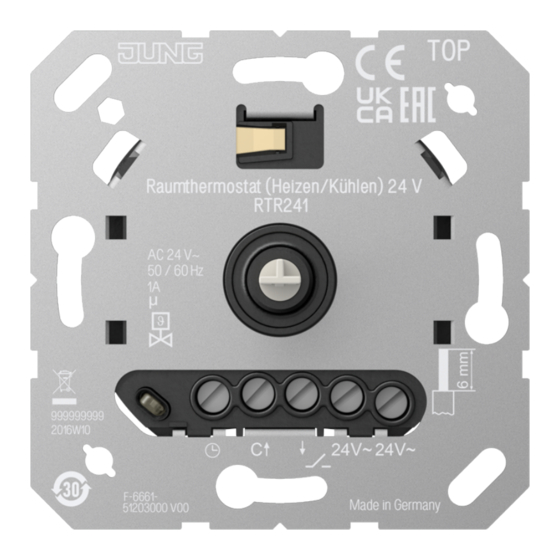
- Page 1 Operating instructions Room thermostat (heating/cooling) 24 V Art. no. RTR241 ALBRECHT JUNG GMBH & CO. KG Volmestraße 1 58579 Schalksmühle GERMANY Telefon: +49 2355 806-0 Telefax: +49 2355 806-204 kundencenter@jung.de 16.09.2022 82405003 J0082405003 www.jung.de...
-
Page 2: Table Of Contents
Room thermostat (heating/cooling) 24 V Table of Contents Safety instructions ...................... 3 Device components...................... 3 Intended use ........................ 3 Product characteristics ...................... 4 Functional description ....................... 4 Operation .......................... 5 Information for electrically skilled persons ................ 7 Commissioning ...................... 9 Technical data ......................... 11 Warranty.......................... 11 82405003 2 / 12 16.09.2022 J0082405003... -
Page 3: Safety Instructions
Room thermostat (heating/cooling) 24 V Safety instructions Electrical devices may only be mounted and connected by electrically skilled persons. Serious injuries, fire or property damage possible. Please read and follow manual fully. Danger of electric shock. During installation and cable routing, comply with the regu- lations and standards which apply for SELV circuits. -
Page 4: Product Characteristics
Room thermostat (heating/cooling) 24 V Product characteristics – Manually setting a comfort temperature – Manually switching off the temperature control – Input terminal for activation of ECO temperature via central clock – Input terminal for activating the cooling mode via central control –... -
Page 5: Operation
Room thermostat (heating/cooling) 24 V Controller adaptation Depending on the heating system, the control behaviour can be adjusted. Pulse width modulated control (factory setting): Optimised for electrothermal valve drives (see Technical data): The output is not permanently actuated, but for a time period (pulse width) that depends on the difference between setpoint and actual tem- perature. - Page 6 Room thermostat (heating/cooling) 24 V In the middle position, the device regulates to approx. 20 °C setpoint temperat- ure. The room temperature reached depends on the installation location of the device and the ambient conditions. The lowest setpoint temperature is approx.
-
Page 7: Information For Electrically Skilled Persons
Room thermostat (heating/cooling) 24 V Activate/deactivate permanent LED operation The status LED lights up with reduced brightness during the active heating or cooling phase. ■ Press the control knob for longer than 10 seconds until the LED lights up or flashes in the colour magenta. - Page 8 Room thermostat (heating/cooling) 24 V Connecting and fitting the device Image 2: Connection example of the insert Image 3: Clampable conductor cross-section ■ Connect electrothermal valve drive (10) to insert (1) according to connection diagram (see figure 2). Observe the conductor cross-sections (see figure 3). ■...
-
Page 9: Commissioning
Room thermostat (heating/cooling) 24 V The unit calibrates itself within the first 90 minutes. Control deviations are pos- sible during this period. Commissioning Setting the control mode and valve type Default setting: – Pulse width modulated control (PWM) – Valve type deenergised closed (NC) This setting can be used with most heating systems without adaptation. - Page 10 Room thermostat (heating/cooling) 24 V Image 4: Setting the temperature limit (before/after) ■ Pull the control knob off the central plate so that the adjustment rings are vis- ible (see figure 4). Pulling off is done by hand or with a suitable tool, e.g. vacuum lifting tool or key cap puller.
-
Page 11: Technical Data
100 m Controller class (EU 811/2013) Contribution to energy efficiency Warranty The warranty is provided in accordance with statutory requirements via the specialist trade. ALBRECHT JUNG GMBH & CO. KG Volmestraße 1 58579 Schalksmühle GERMANY 82405003 11 / 12 16.09.2022... - Page 12 Room thermostat (heating/cooling) 24 V Telefon: +49 2355 806-0 Telefax: +49 2355 806-204 kundencenter@jung.de www.jung.de 82405003 12 / 12 16.09.2022 J0082405003...


Need help?
Do you have a question about the RTR241 and is the answer not in the manual?
Questions and answers