Advertisement
SAFETY
The following symbols appear on the product:
 |  Attention! Refer to Manual. Attention! Refer to Manual. |
 | Application around and removal from UNINSULATED HAZARDOUS LIVE conductors is permitted. |
 | Double/Reinforced Insulation. |
 | Complies with the relevant European standards. |
 | Do not dispose of this product as unsorted municipal waste. Contact a qualified recycler for disposal. |
To avoid electric shock:
- Use caution during installation and use of this product; high voltages and currents may be present in the circuit under test.
- This product must be used only by qualified personnel practicing applicable safety precautions.
- Do not use the product if damaged.
- Always connect the probe to the scope device before installing it around the conductor.
- Do not hold the probe anywhere beyond the tactile barrier:
see Fig. 1.
SPECIFICATION
Electrical data
(All accuracies stated at 23°C ± 1°C)
Nominal current: 200 / 2000 A AC peak or DC
Measuring range (s): 200 / 2000 A
Overload capacity: 2200 A (60 s)
Output sensitivity: 10 / 1 mV/A
Accuracy1) (0 – 200/1500 A) ± 1% of rdg ± 100 / ± 500mA
Accuracy1) (1500 – 2000 A) ± 5% of reading
Resolution: ± 100 / ± 500 mA
Gain variation: ± 0.15% of reading/°C
Frequency range:
DC to 20 kHz (-1 dB)
IRMS x f ≤ 400,000
Power supply:
9 V Alkaline battery
PP3, MN 1604
or IEC6LR61
Load impedance (minimum): > 100 k and 100 pF
General data
Conductor size: 32 mm diameter
Output cable and connectors:
2 m long coax terminated
with safety BNC connector
Operating temperature: 0°C to +50°C
Storage temperature with Battery removed: -20°C to +85°C
1)Accuracy quoted is for conductor in centre of aperture
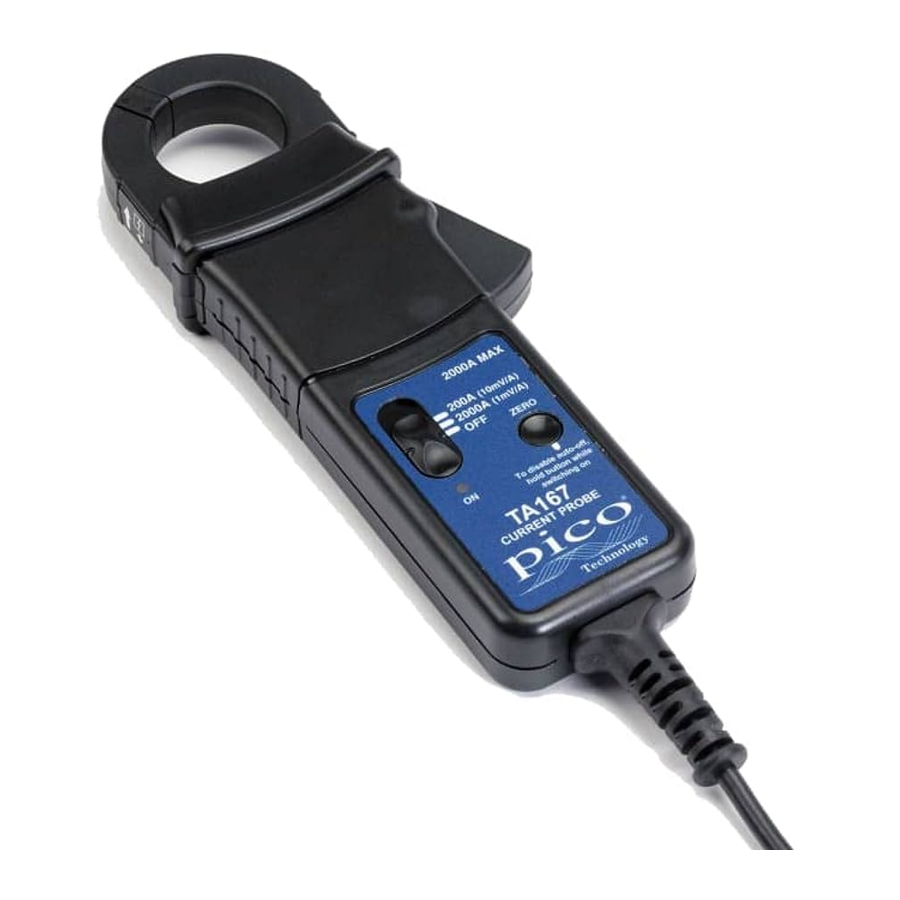
Parts and Features

Fig 1
- Jaws
- Conventional current direction
- Tactile Barrier
- Battery cover
- Battery cover screw
- Jaw trigger
- ON/OFF and Range switch
- Auto zero button
- LED
OPERATING INSTRUCTIONS
Switch On
When the probe is switched on to the required measuring range, the green LED will illuminate. The LED starts flashing when the battery voltage is too low for normal operation and warns the user that it requires changing. This procedure is described below.
Auto Zero
The output zero offset voltage of the probe may change due to thermal shifts and other environmental conditions. Select the required measuring range and to null the output voltage depress the Auto Zero button. Ensure that the probe is away from the current carrying conductor whilst the probe is being nulled.
Current Measurement
- Switch on the probe by selecting the required measuring range and check that the green LED is lit.
- Connect the output lead to the oscilloscope,
- Zero the probe using the Auto Zero button.
- Clamp the jaws of the probe round the conductor ensuring a good contact between the closing faces of the jaws.
- Observe and take measurements as required. Positive output indicates that the current flow is in the direction shown by the arrow on the probe.
Auto Power OFF
In order to save battery life, the probe will automatically switch itself off after approximately 10 minutes. To disable the Auto power off function, Switch Off the probe and Switch On whilst pressing the auto zero button. The red LED will illuminate and the probe will stay ON until switched off again.
Battery Replacement
The green or red LED will flash when the minimum operating voltage is approached. Refer to Fig 1. Use the following procedure:
SAFETY WARNING
Before removing the battery cover, ensure that the probe is disconnected from the oscilloscope and remote from any live electrical circuit.
Unclamp the probe from the conductor, turn it off using the On - Off switch and disconnect the output leads, from external equipment.
Loosen the captive screw which secures the battery cover. Lift the cover through 30° and pull it clear of the probe body as shown in Fig 1. Replace the battery and re-fit the battery cover and fasten the screw.
Fit only Type 9 V PP3 Alkaline (MN 1604).

Documents / Resources
References
Download manual
Here you can download full pdf version of manual, it may contain additional safety instructions, warranty information, FCC rules, etc.
Advertisement


Need help?
Do you have a question about the TA167 and is the answer not in the manual?
Questions and answers