Advertisement
Quick Links
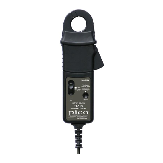
TA189
AC / DC
CURRENT CLAMP
User Guide
SAFETY
The following symbols appear on the product:
Attention! Refer to manual.
Application around and removal from
UNINSULATED HAZARDOUS LIVE conductors
is permitted.
Double/reinforced insulation.
Complies with the relevant European standards.
Do not dispose of this product as unsorted
municipal waste. Contact a qualified recycler for
disposal.
Read all instructions completely before using
this product.
To avoid electric shock:
• Use caution during installation and use of this product.
High voltages and currents may be present in circuit under
test.
• This product must be used only by qualified personnel
practising applicable safety precautions.
• Do not use product if damaged.
• Always connect clamp to display device before it is installed
around the conductor.
• Always ensure that the clamp is removed from any live
electrical circuit, and that leads are disconnected before
removing the battery cover.
• Do not hold the clamp anywhere beyond the tactile barrier
see Fig. 1.
SPECIFICATION
Electrical data
(All accuracies stated at 23°C ± 1°C)
Nominal current ................. 30 A AC
PEAK
Measuring range (s) ........... 30 A
Overload capacity .............. 500 A (60 s)
Output sensitivity ................ 100 mV/A
Accuracy ............................ ± 1% of reading ± 2 mA
Resolution .......................... ± 1 mA
Gain variation ..................... ±0.01% of reading/°C
Frequency range
Power supply .....................
Load impedance (minimum) > 100 k
General data
Conductor size ...................
Output cable and connectors 2 m long coax terminated with
Operating temperature .......
Storage temperature with
battery removed .................
1)
Accuracy quoted is for conductor in centre of aperture
1
0.5
0
-0.5
-1
-1.5
-2
-2.5
-3
1
3
4
7
9
or DC
1)
.............
DC to 100 kHz (0.5 dB)
9 V Alkaline battery
PP3, MN 1604
or IEC6LR61
and
100 pF
25 mm diameter
safety BNC connector
0°C to +50°C
-20°C to +85°C
Typical frequency plot
10
100
1000
10000
100000
Frequency (Hz)
2
4
5
6
8
1. Jaws
2. Conventional current direction
3. Tactile barrier
4. Battery cover
5. Battery cover screw
6. Jaw trigger
7. On/off switch
8. Auto zero button
9. LED
Fig. 1.
0
-5
-10
-15
-20
Gain
Phase
Advertisement

Related Manuals for PICO TA189


Summary of Contents for PICO TA189
- Page 1 Load impedance (minimum) > 100 k 100 pF Attention! Refer to manual. General data Application around and removal from UNINSULATED HAZARDOUS LIVE conductors TA189 Conductor size ....25 mm diameter is permitted. Output cable and connectors 2 m long coax terminated with safety BNC connector Double/reinforced insulation.
-
Page 2: Operating Instructions
Auto Zero button. The red LED will illuminate and be a suitably qualified or authorised person. Ensure that your Pico Technology Limited the clamp will stay ON until switched off again. fingers are behind the protective barrier (see Fig. 1) when using the clamp.
Need help?
Do you have a question about the TA189 and is the answer not in the manual?
Questions and answers