Table of Contents
Advertisement
Quick Links
Advertisement
Table of Contents

Subscribe to Our Youtube Channel
Related Manuals for PICO TA466


Summary of Contents for PICO TA466
- Page 1 TA466 Two-pole voltage detector User’s guide www.picoauto.com...
-
Page 2: Table Of Contents
Continuity check ........................6 3.9. Pocket lamp function ....................... 6 3.10. Battery replacement ......................... 6 3.11. General maintenance........................ 7 3.12. Periodic maintenance ....................... 7 3.13. Cable replacement and checks: ....................7 3.14. Connecting accessories ......................7 3.15. Technical specifications ......................8 Copyright © 2020 Pico Technology Ltd. All rights reserved. DO340-1... -
Page 3: Description
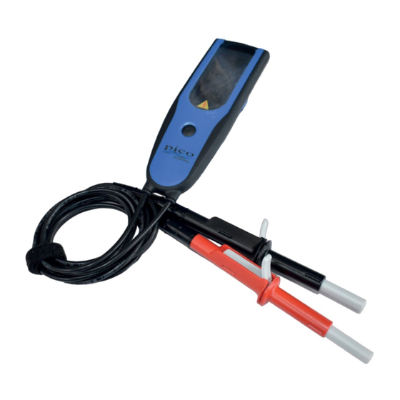
TA466 Two-pole Voltage Detector 1. Description The TA466 Two-pole voltage detector can be used for carrying out no-voltage checks, and for measuring up to 690 V AC and up to 950 V DC. It is designed to be easily handled. The test probes are clipped to the underside of the casing for storage and for easy use on standard European outlets (centre-to-centre distance: 19 mm). -
Page 4: Operating Instructions
• The presence of an alternating voltage is confirmed by the illumination of the symbol. • The presence of a direct voltage is confirmed by the illumination of the symbol. • The display will automatically stop as soon as the measuring probes are disconnected. • The display has a resolution of 1 V. • The unit has an accuracy of (± 5% ± 2 digits). Note: Do not use the verification indicators alone for voltage measurements. Copyright © 2020 Pico Technology Ltd. All rights reserved. DO340-1... -
Page 5: Polarity Check (Direct Voltage)
• The device is ready for the next sequence when the symbol blinks. Step 2: • Move the black test probe to phase 3: • If the symbol rotation is clockwise, the phase order is as well (L1, L2, L3). • If the symbol rotation is counter-clockwise, the phase order is as well (L3, L2, L1). • If the symbol disappears or keeps blinking, the three-phase system is not balanced. Repeat the two steps to confirm the result. Note 1: You only have 10 seconds to carry out Step 2. Note 2: In the case of counter-clockwise order, we advise you to check the phase shift again by reversing the order of connections 2 and 3 to confirm the phase sequence. Note 3: To start a new check (from Step 1 again), disconnect the device from the source you are checking and wait until the symbol stops blinking. DO340-1 Copyright © 2020 Pico Technology Ltd. All rights reserved. -
Page 6: Continuity Check
• A rapidly pulsating audible signal. A continuity resistance of more than 100 Ω will cause the voltage detector to show no indication. 3.9. Pocket lamp function Press the test button. 3.10. Battery replacement Make sure that the device is disconnected from all voltage sources. The battery must be replaced when the correct operation check (self-test) fails. 1. Use a Pozidriv screwdriver to undo the three screws on the bottom cover. 2. Remove the bottom cover. 3. Insert two AAA batteries (LR03: 1.5 V), make sure you observe the polarity indicated on the battery holder. 4. Replace the bottom cover. Take care to reposition the joint before you tighten the three screws. 5. Secure with an adequate torque (about 0.75 Nm). Note 1: Remove the batteries if the voltage detector will be unused for a longer period of time. Note 2: The batteries have an expiration date indicated on the body. Replace them before they expire. Copyright © 2020 Pico Technology Ltd. All rights reserved. DO340-1... -
Page 7: General Maintenance
The connecting leads are equipped with a wear indicator. If the white insulating layer appears on the cable, the connecting leads must be replaced. Unauthorised staff must not disassemble the voltage detector. 3.13. Cable replacement and checks: The two-pole voltage tester is a safety test tool and must not be used when damaged or with visible wear. It is required to be checked by the manufacturer every six years. Because it is a safety test tool, the checks and replacements must be carried out at the factory. Please contact your local Pico representative to arrange the applicable service for your device. 3.14. Connecting accessories Use only accessories (cables, clamps, etc.) that comply with EN 61010-031. DO340-1 Copyright © 2020 Pico Technology Ltd. All rights reserved. -
Page 8: Technical Specifications
Pico Technology GmbH James House 320 N Glenwood Blvd Ihm Rehwinkel 6 Colmworth Business Park Tyler 30827 Garbsen St. Neots TX 75702 Germany Cambridgeshire United States PE19 8YP United Kingdom Tel: +44 (0) 1480 396395 Tel: +1 800 591 2796 Tel: +49 (0) 5131 907 6290 Email: support@picotech.com Email: support@picotech.com Email: info.de@picotech.com Pico Technology is an internationally registered trade mark of Pico Technology Ltd. www.picoauto.com Copyright © 2020 Pico Technology Ltd. All rights reserved. DO340-1...
Need help?
Do you have a question about the TA466 and is the answer not in the manual?
Questions and answers