Table of Contents
Advertisement
Quick Links
Item Checklist
This item checklist is only available for retail
market. Completely check your package, If you
discover damaged or missing items, contact
your retailer.
K8N4/K8N4U series mainboard
QDI Utility CD
1HD ribbon cable
User' s manual
I/O shield(option)
USB cable(option)
Notice
The information in this document is subject to
change in order to improve reliability, design, or
function without prior notice and does not repre-
sent a commitment on the part of this company.
In no event will we be liable for direct, indirect,
special, incidental, or consequential damages
arising out of the use or the possibility of such
damages.
All trademarks are the property of their respec-
tive owners.
If you need any further information, please visit
our web-site: " www.qdigrp.com" .
Advertisement
Table of Contents

Related Manuals for QDI K8N4 Series


Summary of Contents for QDI K8N4 Series
- Page 1 This item checklist is only available for retail market. Completely check your package, If you discover damaged or missing items, contact your retailer. K8N4/K8N4U series mainboard QDI Utility CD 1HD ribbon cable User’ s manual I/O shield(option) USB cable(option) Notice...
- Page 2 The following products have been tested by us with the listed standards and found in compliance with the council EMC directive 89/336/EEC. It is demonstrative for the compliance with this EMC Directive. Submittor: QDI Technology Limited 23Floor, Lincoln House, Taikoo Place 979 King’ s Road, Quarry Bay, HONG KONG Product:...
- Page 3 Declaration of conformity Trade Name: QDI Computer ( U. S . A. ) Inc. Model Name: K8N4/K8N4U Responsible Party: QDI Computer ( U. S. A.) Inc. Address: 41456 Christy Street Fremont, CA 94538 Telephone: (510) 668-4933 Facsimile: (510) 668-4966 Equipment Classification:...
-
Page 4: Table Of Contents
CONTENTS Chapter 1 Introduction ..............1 Key Features ..............2 Chapter 2 Installation Instructions............4 External Connectors ............5 PS/2 Keyboard /Mouse Connector ........5 USB1, USB2,USB3 ,USB4 and LAN Connectors ....5 Parallel Port , Serial Port Connectors(COM1) and SPDIF OUT Connector .............. - Page 5 CONTENTS Chapter 3 BIOS Description..............17 AWDFLASH.EXE ...............18 AWARD BIOS Description..........19 Appendix QDI Utility CD..............30 Using 4-/6-Channel Audio..........40 Layout...
- Page 6 Caution Be sure to unplug the AC power supply before adding or removing expansion cards, RAM or other system peripherals, otherwise your mainboard and RAM might be seriously damaged. Caution Be sure to add some Silicone Grease between the CPU and the heatsink to keep them fully contacted to meet the heat sink require- ment.
-
Page 7: Chapter 1 Introduction
Chapter 1 Chapter 1 Introduction K8N4/K8N4U series of mainboards utilize nFORCE4- 4X / nFORCE4-Ultra chipset, providing a fully compatible, high performance and cost-effective ATX platform. The new integrated technologies, together with AC’ 97 audio, 10 USB 2.0, 4 SATA, and ATA133/100/66/33, give customers an advanced, multimedia solution at reasonable price. -
Page 8: Key Features
Introduction Form factor ATX form factor of 305mm x 244mm Microprocessor Supports AMD Socket 939 CPU Supports HyperTransport technology System memory Supports DDR266/333/400 SDRAM Supports 128Mb/256Mb/512Mb/1Gb technology up to 4GB Provides four 184-pin DDR SDRAM interfaces PCI Express x16 Graphics PCI Express 1.0a specification compliant Supports one PCI Express x16 port PCI Express x1 Ports(optional) - Page 9 Chapter 1 Advanced features PCI 2.3 Specification Compliant Supports Windows 98/2000/ME/XP soft-off Onboard SATA Four SATA devices including SATA HDD device Supports 150MBps(nFORCE4-4X chipset) transfer rate. Supports 300MBps(nFORCE4-Ultra chipset) transfer rate. BIOS Licensed advanced AWARD(Phoenix) BIOS, supports flash ROM, plug and play ready Supports IDE CDROM/USB boot up.
-
Page 10: Installation Instructions
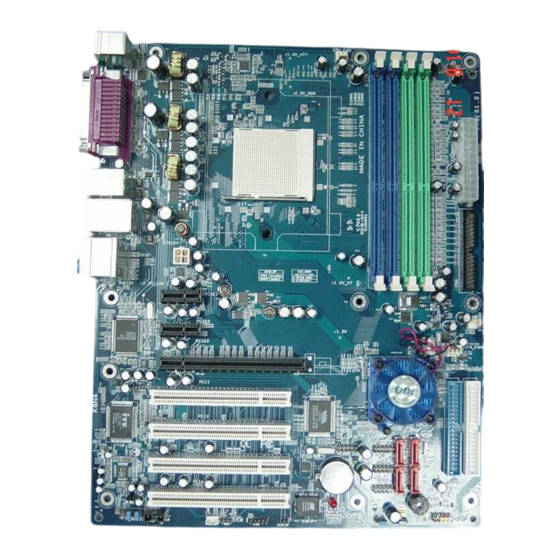
Installation Instructions Chapter 2 Installation Instructions This section covers External Connectors and Jumper Settings. Refer to the mainboard layout chart for locations of all jumpers, external connectors, slots and I/O ports. Furthermore, this section lists all necessary connector pin assignments for your reference. The par- ticular state of the jumpers, connectors and ports are illustrated in the following figures. -
Page 11: External Connectors
Chapter 2 External Connectors PS/2 Keyboard/Mouse Connector PS/2 keyboard connector is for the usage of PS/2 keyboard. If using a standard AT size keyboard, an adapter should be used to fit this connector. PS/2 mouse connector is for the usage of PS/2 mouse. PS/2 Mouse connector PS/2 Keyboard connector USB1, USB2, USB3, USB4 and LAN Connectors(optional) -
Page 12: Line-In Jack, Mic-In Jack And Speaker-Out Jack
Installation Instructions Line-in jack, Microphone-in jack and Speaker-out jack The Line-in jack can be connected to devices such as a cassette or minidisc player to playback or record. The Microphone-in jack can be connected to a microphone for voice input. The Speaker-out jack allows you to connect speakers or headphones for audio output from the internal amplifier. -
Page 13: Dual Channel Introduce
Chapter 2 Dual channel introduce DIMM1 DIMM2 DIMM3 DIMM4 To using dual channel DDR, DIMM1/DIMM2 is a combination,DIMM3/DIMM4 is the other combination.The following figure illustrates the dual channel DDR installation: 1. two same memory DIMM1 DIMM2 DIMM3 DIMM4 DIMM1 DIMM2 DIMM3 DIMM4... - Page 14 Installation Instructions 2. four same memory DIMM1 DIMM2 DIMM3 DIMM4 DIMM1 DIMM2 DIMM3 DIMM4 K8N4/K8N4U...
-
Page 15: Atx 12V Power Supply Connectors & Power Switch
Chapter 2 ATX 12V Power Supply Connector & Power Switch (POWER Switch) The power switch (POWER SW) should be connected to a momentary switch. When powering up your system, first turn on the mechanical switch of the power supply (if one is provided), then push once the power switch. -
Page 16: Power Led Connector (Pwr_Led)
Installation Instructions Power LED Connector (PWR_LED) When the system is in S1,S0 status, the LED is on. When the system is in S3, S5 status, the LED is off. The connector has an orientation. reserve PWR LED(+) HDD LED(+) HDD LED(-) PWR LED(-) G N D P O W E R... -
Page 17: Usb5_6; Usb7_8;Usb9_10
Chapter 2 USB5_6; USB7_8; USB9_10 Besides USB1,2,3,4 on the back panel, K8N4/K8N4U series of mainboards also have three 10-pin headers on board which may connect to front panel USB cable( optional ) to provide additional six USB ports. UD0- UD1- USB5_6 UD0+ UD1+... -
Page 18: Audio Connectors(Cd_In)(Optional)
Installation Instructions Audio Connectors (CD_IN)(optional) CD_IN is Sony standard CD audio connector, it can be connected to a CD-ROM drive through a CD audio cable. CD Left Channel CD_IN CD Right Channel Front IEEE 1394 port(1394)(optional) Besides one 1394 port on the back panel, the mainboard also have one 10-pin headers on board to provide additional IEEE 1394 port. -
Page 19: Wake_Up On Lan(Wol)(Optional)
Chapter 2 Wake-Up On LAN (WOL)(optional) Through the Wake-Up On LAN function, a wake event occurring from the network can wake up the system. If this function is to be used, please be sure an ATX 12V power supply and a LAN adapter which supports this function are used. Then connect this header to the relevant connector on the LAN adapter, set “... -
Page 20: Audio Interface(F_Audio)
Installation Instructions Audio Interface(F_AUDIO)(Optional) The audio interface provides two kinds of audio output choices: the FrontAudio and the RearAudio. Their priority level is as sequence. When the FrontAudio is available, the RearAudio( in-case speakers ) will be cut off. An onboard amplifier is provided for the earphone. -
Page 21: Jumper Settings
Chapter 2 Jumper Settings Jumpers are located on the mainboard, the clear CMOS jumper JCC, enable keyboard password power-on function jumper JKB etc. Pin 1 for all jumpers are located on the side with a thick white line (Pin1→ ), referring to the mainboard’ s silkscreen. Jumpers with three pins will be shown as to represent pin1 &... -
Page 22: Bios-Protection Jumper(Bios_Wp)
Installation Instructions BIOS-Protection Jumper (BIOS_WP) If the jumper BIOS_WP is set as closed, the system BIOS is protected from being at- tacked by serious virus such as CIH virus, you will be unable to flash the BIOS to the mainboard in this status. Flash Write Disabled BIOS_WP Flash Write Enabled... -
Page 23: Chapter 3 Bios Description
Chapter 3 Chapter 3 BIOS Description The mainboard uses AWARD BIOS Setup program that provides a Setup utility for users to modify the basic system configuration. The information is stored in CMOS RAM so it retains the Setup information even if the power is turned off. This chapter provides you with the overview of the BIOS Setup. -
Page 24: Awdflash.exe
1. Create a bootable system floppy diskette by typing Format A:/s from the DOS prompt under DOS6.xx or Windows 9x environment. 2. Copy AWDFLASH.EXE(version>=8 .60aq) from the directory \Utility located on QDI Utility CD to your new bootable diskette. 3. Download the updated BIOS file from the Website (http://www.qdigrp.com). Please be sure to download the suitable BIOS file for your mainboard. -
Page 25: Award Bios Description
Chapter 3 AWARD BIOS Description Entering Setup Power on the computer, when the following message briefly appears at the bottom of the screen during the POST (Power On Self Test), press <Del> key to enter the AWARD BIOS CMOS Setup Utility. Press <Del>... - Page 26 MODE HDD access mode QDI Innovation Features This section describes QDI innovation EASY technology. Advanced BIOS Features This section allows you to configure your system for basic operation. You have the opportunity to select the system’ s default speed, boot-up sequence, keyboard operation, shadowing and security.
- Page 27 Chapter 3 Set Supervisor/User Password Changes, sets, or disables password. It allows you to limit access to the system and the setup program.When this function is selected, the following message appears at the center of the screen to assist you in creating a password. ENTER PASSWORD Type the password, up to eight characters, and press <Enter>.
- Page 28 BIOS Description QDI Innovation Features QDI Innovation Features Menu The following indicates the options for each item and describes their meaning. Item Option Description [BootEasy Setting] QDI BootEasy feature Enabled PC boot in rapid speed, without any redunant feature waiting for the display- ing of starting OS.
- Page 29 Chapter 3 Hammer Fid Control startup Set CPU ratio frequency. x4 800Mhz x5 1000Mhz x6 1200Mhz x7 1400Mhz x8 1600Mhz ..Hammer Vid Control startup Set CPU voltage. 1.550V ..0.825V [BIOS-ProtectEasy Setting] BIOS Protect Enabled This option is for protecting the system Disabled BIOS, when enabled, writing to BIOS area is to be discarded.
- Page 30 BIOS Description Advanced BIOS Features Advanced BIOS Features Menu The following indicates the options for each item and describes their meaning. Item Option Description Removable Device Priority Press Enter Enter to set removable device priority. Hard Disk Boot Priority Press Enter Enter to set hard disk boot priority.
- Page 31 Chapter 3 Power Management Setup Power Management Setup Menu The following indicates the options for each item and describes their meaning. Item Option Description ACPI function Enabled Enable ACPI function. Disabled Disable this function. ACPI Suspend Type S1(POS) Select the ACPI suspend type. S3(STR) S1&S3 Power-on by Alarm...
- Page 32 BIOS Description Integrated Peripherals Integrated Peripherals Menu The following indicates the options for each item and describes their meaning. Item Option Description IDE Function Setup Press Enter Press enter to set On-Chip IDE device. OnChip IDE Channel0 Enabled Enable onchip IDE channel0. Disabled Invalidate this feature.
- Page 33 Chapter 3 RAID Config Press Enter Press enter to set RAID device. OnChip USB V1.1+V2.0 Support onchip USB V1.1 and USB V2.0. V1.1 Support USB V1.1 only. Disabled Invalidate all USB onboard. USB Keyboard Support Enabled Support USB keyboard under legacy OS. Disabled Disabel this function.
- Page 34 BIOS Description UART Mode Select Normal Defines Serial Port as standard serial port. IrDA Supports IRDA mode. ASK IR Supports SHARP ASK-IR protocol with maxi mum baudrate up to 57600bps. UR2 Duplex Mode Half /Full Default is recommended. Onboard Parallel Port 378/IRQ7 Define parallel port address and IRQ 278/IRQ5...
- Page 35 Chapter 3 PC Health Status PC Health Status Menu The following indicates the options for each item and describes their meaning. Item Option Description Shutdown Temperature C/140 The system will shut down automatically C/149 under the ACPI OS when the CPU C/158 temperature reaches the previous setting, C/167...
-
Page 36: Appendix Qdi Utility Cd
Appendix Appendix QDI Utility CD A QDI Utility CD is supplied with this mainboard, the contents contained in it are showed as below: 1. Driver Install Using this choice, you can install all the drivers for your mainboard . You should install the drivers in order, and you need to restart your computer until all the drivers are installed. - Page 37 Appendix SpeedEasy BIOS provides you with a set of basic values for your processor selection instead of the jumper settings. The processor speed can be manually selected on the “ QDI Innovation features” menu screen. BootEasy BootEasy technology enormously improves the long BOOT process time of computers.
- Page 38 Appendix QDI BootEasy(German) BootEasy ist eine Neuentwicklung von QDI, die neue Innovation der QDI Easy- Technologien. Mit der BootEasy- Technologie Technik wird der Bootvorgang nur noch vier bis fünf Sekunden in Anspruch nehmen, bis das Betriebssystem geladen wird. Der Grund fü r die lange Warterei liegt in den Routine-Abfragen, die das BIOS bei jedem Start abarbeitet.
- Page 39 (Consulte el apartado “ Jumper Settings” en el manual de usuario de su placa QDI K8N4/K8N4U en el capí tulo Inserte el procesador en el socket y conecte el ventilador del procesador en el conector de su placa base QDI K8N4/K8N4U marcado como “...
- Page 40 Para má s informació n las funciones de la Bios, consulte el apartado “ BIOS Description” en el manual de usuario de la placa base QDI K8N4/K8N4U). Presione la tecla « F10 » y seleccione la opció n “ Save & Exit Setup” en el menú de configuració n de la Bios para guardar los cambios y reiniciar el sistema.
- Page 41 K8N4/K8N4U (French): Inté gration du systè me : Vé rifier la pré sence de chaque é lé ment dans la boite de la carte mè re de la sé rie QDI K8N4/K8N4U : Une carte mè re de la sé rie QDI K8N4/K8N4U.
- Page 42 10. Raccorder les pé riphé riques externes sur les connecteurs de fond de panier inté gré s à la carte mè re de la sé rie QDI K8N4/K8N4U. Dans ce but il est important de se ré fé rer à la section nommée « Connecteurs externes » du chapitre numéro 2 nommé...
- Page 43 1. Driver Install : Avec cette option, il est possible d’ installer les pilotes de la carte mè re de la sé rie QDI K8N4/ K8N4U aisé ment. Il est important d’ installer les pilotes en respectant l’ ordre pré dé finit et de redé...
- Page 44 Appendix QDI K8N4/K8N4U installazione mainboard (Italian): 1. Assicurarsi che la scatola sia completa: QDI K8N4/K8N4Umainboard, cavo IDE e Floppy, jumpers, manuale dell’ utente della mainboard QDI K8N4/K8N4U e cd-rom drivers. 2. Controllare che il cavo alimentazione proveniente dal computer-case sia sconnesso assicurarsi inolre di aver indossato corretamente il bracciale da polso collegato a massa.
- Page 45 Appendix Dopo questo ultimo passo procedere all’ installazione dei driver delle varie periferiche IL CD CONTENENTE I DRIVER DELLA VOSTRA MAINBOARD QDI E’ CONTENUTO NELLA SCATOLA Installazione driver E possibile installare tutti i driver della Vs. mainboard in modo facile e veloce.
-
Page 46: Using 4-/6-Channel Audio
Appendix Using 4-/6-Channel Audio(4-/6- Channel Audio Interface) The motherboard is equipped with Realtek ALC655 chip, which provides support for 6- channel audio output, including 2 Front, 2 Rear, 1 Center and 1 Subwoofer channel. ALC655 allows the board to attach 4 or 6 speakers for better surround sound effect. The section will tell you how to install and use 4/6-channel audio function on the board. - Page 47 Appendix 6-Channel Analog Audio Output Line Out(Rear Channels) Line Out (Front channels) Line Out(Center & Subwoofer Channels) Description: Both Line In and MIC are converted to Line Out function under 6- channel configuration. K8N4/K8N4U...
- Page 48 Appendix Selecting 4- or 6-Channel Setting 1. Click the audio icon from the window tray at the bottom of the screen. 2. Select any surround sound effect you prefer from the “ Environment” pull-down menu under the Sound Effect tab. Click here and the pull-down menu will appear...
- Page 49 Appendix 4. The following window appears. Headphone Output 2 Channels Output 4 Channels Output Keep UnSelect 6 Channels Output Status 5. Select the multi-channel operation you prefer from No. of Speakers. 6. Click OK Testing the Connected Speakers To ensure 4- or 6-channel audio operation works properly, you may need to test each connected speaker to make sure every speaker work properly.
- Page 50 Appendix Playing KaraOK The KaraOK function will automatically remove human voice (lyrics) and leave me-lody for you to sing the song. The function is applied only for 2-channel audio opera- tion, so make sure channel mode is selected in the “ No. of Speakers” column before playing KaraOK.
- Page 51 The Realtek chip provides 8-channel audio capability to deliver the ultimate audio experience on your PC. First install the Audio driver from the QDI CD that came with the motherboard package. If the Realtek audio software is correctly installed,you will find the SoundEffect icon on the tackbar.
- Page 52 Appendix SPDIF Options The SPDIF options allows you to change your SPDIF output settings. To set the SPDIF options: 1. from the Realtek Audio Control Panel, click the SPDIF button. 2. click the shortcut buttons to change the SPDIF settings. 3.
- Page 53 Appendix 3D Audio Demo The option shows a demo of the 3D Audio functions. To start the 3D Audio Demo: 1. from the Realtek Audio Control Panel, click the 3D Audio Demo button. 2. click the option buttons to change the sound, moving path or EAX settings. 3.
- Page 54 Appendix Microphone Effect The option allows you to set microphone effect. To start the microphone effect: 1. from the Realtek Audio Control Panel, click the microphone effect button. 2. you can set microphone effect: Noise Suppression or Stered Microphone. 3. click the Exit button on the upper-ring hand corner of the window to exit. K8N4/K8N4U...
Need help?
Do you have a question about the K8N4 Series and is the answer not in the manual?
Questions and answers