Table of Contents
Advertisement
Quick Links
Advertisement
Table of Contents

Related Manuals for Vertiv Liebert EXL S1 480V


Summary of Contents for Vertiv Liebert EXL S1 480V
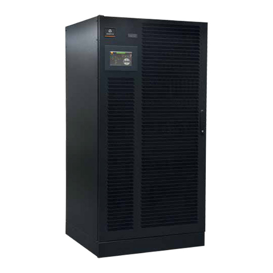
- Page 1 Liebert® EXL S1 480V User Manual...
- Page 2 Liebert EXL S1 480V UNINTERRUPTIBLE POWER SUPPLY USER MANUAL 10H52264UM60 - rev. 6...
- Page 3 Liebert EXL S1 rights, including rights translation, reproduction by printing, copying or similar methods, even of parts, are reserved. Transgressors will be liable for damages. All rights, including rights deriving from patent license or registration of utility model or design, are reserved.
-
Page 4: Table Of Contents
Liebert EXL S1 1. INTRODUCTION..................... 5 1.1. Notes to the CE Declaration of Conformity ..................5 1.2. Symbols and pictograms ..........................5 1.3. Terms used ................................. 6 1.4. Glossary................................6 1.5. Documentation structure........................... 6 1.6. Pre-installation Planning ..........................6 1.7. Preliminary Checks ............................7 1.8. - Page 5 Liebert EXL S1 6.1. Placement into service..........................67 6.2. Communication between UPS blocks....................68 6.3. Parallel switching procedures ......................... 68 7. MAINTENANCE ..................... 73 7.1. Limited Life Components..........................73 7.2. Disposal of batteries............................74 7.3. Decommissioning............................74 8. OPTIONS ........................ 75 8.1.
-
Page 6: Introduction
Additional information regarding adherence to these directives is included in the appendices NSR and EMC to the Declaration of Conformity. If needed, the Declaration of Conformity can be requested to Vertiv. 2011/65/EU Directive of the council for adapting the legal regulations of member states on the restriction of the use of certain hazardous substances that can be used in the manufacture of electrical and electronic equipment. -
Page 7: Terms Used
Introduction Liebert EXL S1 1.3. Terms used 1.3.1. Service Bypass A switch that provides continuous supply to the load via the bypass input power line during maintenance work; also referred to as the maintenance bypass. 1.3.2. Static Bypass Switch A thyristor switch which connects the load directly to the power line; also referred to as a static switch or static bypass. -
Page 8: Preliminary Checks
(see chap. 9. on page 79). Notice Vertiv will not accept liability or pay costs, fees, or damages arising from storing or operating the UPS outside of the specified environmental, performance, or operating ranges and conditions as set forth herein or in other product documentation. Please contact Vertiv Technical Support for more information. - Page 9 Introduction Liebert EXL S1 removed by a Vertiv Customer Engineer during startup and must be reinstalled when the UPS is not operating during construction activities. Do not remove the protection fixed to the roof; it must be removed only before the start up...
- Page 10 UPS. It is the responsibility of the installer to ensure no conductive material enters the unit. Installer will be billed at Vertiv’s prevailing labor wage for any cleaning or failure as a result of debris entering the unit 1.8.2.
- Page 11 Introduction Liebert EXL S1 BLANK PAGE User Manual 10H52264UM60 - Rev. 6 - 12/2021...
-
Page 12: Preparation For Use
Liebert EXL S1 Preparation For Use 2. PREPARATION FOR USE 2.1. Transport The equipment must be kept upright at all times and handled with care. Damage may be caused if it is dropped or subjected to severe impact. When moving the equipment with a forklift, secure it against tilting. - Page 13 Preparation For Use Liebert EXL S1 Check all packaging materials to ensure that no important items are discarded. Once the packaging has been removed, the UPS must be taken off the pallet by removing the screws as illustrated in Fig. 1 or by removing the L profile as illustrated in Fig.
-
Page 14: Liebert Exl S1 1000/1200Kva Cabinets Assembly Procedure
Liebert EXL S1 Preparation For Use 2.4. Liebert EXL S1 1000/1200kVA cabinets assembly procedure The Liebert EXL S1 1000/1200kVA is composed by two cabinets, one contains the modules and one contains the switches, and they must be assembled and connected together as first step of the installation following the below procedure. - Page 15 Preparation For Use Liebert EXL S1 In the modules cabinet, remove the two lexan particulars in red and the iron ones indicated below in blue. User Manual 10H52264UM60 - Rev. 6 - 12/2021...
- Page 16 Liebert EXL S1 Preparation For Use Assemble the iron particulars in red as indicated by the arrows using supplied hexagonal head screws M6x30 + grower + washer. User Manual 10H52264UM60 - Rev. 6 - 12/2021...
- Page 17 Preparation For Use Liebert EXL S1 Connect the busbars of modules cabinet to the switches terminals in red as indicated by the arrows using supplied hexagonal head screws M12x35 + grower + washer. For a correct connection and installation of the busbars use contact grease. For tightening torque, please refer to Table 3.
- Page 18 Liebert EXL S1 Preparation For Use Connect the signal wiring to the switches auxiliary contacts QS1, QS2 and QS4 (pin COM and pin N.O.), as indicated in the functional schematic. Reassemble the two lexan particulars and the iron one previously removed in the modules cabinet;...
-
Page 19: Environmental Conditions
Preparation For Use Liebert EXL S1 2.5. Environmental conditions The UPS must be installed vertically, on a level and even surface, and in an area protected from extremes of temperature, water and humidity. Do not stack the units or place objects on top of them. The operating temperature range of the UPS is 0°C-40°C. -
Page 20: Access To Service Area And Cooling System
Liebert EXL S1 Preparation For Use 2.6. Access to service area and cooling system When installed, the UPS can only be accessed from the front. All front doors have a maximum aperture of 90°. The area must have sufficient space for installation procedures to be carried out. Access doors must be wide enough to permit unobstructed transport of the device (chap. -
Page 21: Installation And Footprint
Preparation For Use Liebert EXL S1 2.7. Installation and footprint The overall external dimensions of the UPS are listed on the final data table There are no restrictions on where you can position the UPS. The rear of the machine can be positioned against a wall. On machines with connecting cables at the rear, allow room for the curvature of the cables. - Page 22 Liebert EXL S1 Preparation For Use FRONT Figure 5 - Liebert EXL S1 800kVA bottom view (footprint and floor mounting holes) User Manual 10H52264UM60 - Rev. 6 - 12/2021...
- Page 23 Preparation For Use Liebert EXL S1 FRONT Figure 6 - Liebert EXL S1 800kVA upper view (gland plate) User Manual 10H52264UM60 - Rev. 6 - 12/2021...
- Page 24 Liebert EXL S1 Preparation For Use FRONT Figure 7 - Liebert EXL S1 800kVA upper view (doors open) User Manual 10H52264UM60 - Rev. 6 - 12/2021...
- Page 25 Preparation For Use Liebert EXL S1 FRONT Figure 8 - Liebert EXL S1 1000/1200kVA bottom view (gland plate) User Manual 10H52264UM60 - Rev. 6 - 12/2021...
- Page 26 Liebert EXL S1 Preparation For Use FRONT Figure 9 - Liebert EXL S1 1000/1200kVA bottom view (footprint and floor mounting holes) User Manual 10H52264UM60 - Rev. 6 - 12/2021...
- Page 27 Preparation For Use Liebert EXL S1 FRONT Figure 10 - Liebert EXL S1 1000/1200kVA upper view (gland plate) User Manual 10H52264UM60 - Rev. 6 - 12/2021...
- Page 28 Liebert EXL S1 Preparation For Use FRONT Figure 11 - Liebert EXL S1 1000/1200kVA upper view (doors open) User Manual 10H52264UM60 - Rev. 6 - 12/2021...
- Page 29 Preparation For Use Liebert EXL S1 BLANK PAGE User Manual 10H52264UM60 - Rev. 6 - 12/2021...
-
Page 30: Installation
Liebert EXL S1 Installation 3. INSTALLATION 3.1. Electrical preparations Warning For reasons of safety, the secondary access panel MUST NOT BE REMOVED. If, for any reason, it is necessary to remove this panel, the entire installation must be switched off and de-energized; otherwise complete safety cannot be guaranteed. The UPS is connected to 480V three-phase power lines;... -
Page 31: Currents And Suggested Cable Sizes
Notice Tinned lugs are required if aluminum cable is to be used. If aluminum cable is to be used, top and bottom cable entry may be required. Contact Vertiv Technical Support for more information. Notice All wiring must be selected in accordance with national and local electrical codes, and coordinated with protection devices installed ahead of the UPS. - Page 32 Liebert EXL S1 Installation Table 2: Currents and maximum cable sizes UPS devices (kVA) 1000 1200 Primary Power line Max. current (A) 1200 1500 1800 4x300 6x300 6x300 Max. number of conductors connectable to BUS-BAR & cross section (mm Screw size Bypass Power line/Load Nominal current (A) 1203...
-
Page 33: Physical Appearance
Installation Liebert EXL S1 3.3. Physical appearance Legend: • QS1 = PRIMARY MAINS INPUT SWITCH • QS2 = BYPASS MAINS SWITCH • QS4 = OUTPUT SWITCH ST. SW. MODULE MODULE “B” RECT/INV MODULE “A” RECT/INV PHASE U PHASE U MODULE “A” RECT/INV MODULE “B”... - Page 34 Liebert EXL S1 Installation Figure 13 - Liebert EXL S1 1000/1200kVA - front view User Manual 10H52264UM60 - Rev. 6 - 12/2021...
-
Page 35: External Protection Devices
Installation Liebert EXL S1 3.4. External protection devices This device is equipped with manual switches intended only for Service Bypass and Internal Service operations. It is therefore essential that the customer install external protection devices at the installation site. These must be installed near the unit and labelled as the line power separation device for the UPS (see IEC/EN 62040-1+A1:2013). - Page 36 31. These devices should be installed as close as possible to the battery. • Vertiv recommends installing a local battery disconnect near the battery for safe maintenance. If this is not possible, it is required to use a lock-out tag-out device in the battery room and always check for hazardous voltage before performing maintenance on the UPS.
-
Page 37: Backfeed Protection
Installation Liebert EXL S1 Notice Vertiv will not accept liability or pay costs, fees, or damages resulting from missing or incorrect sizing of the battery protection device(s). Please contact Vertiv Technical Support for more information. Vertiv recommends using a proprietary battery breaker control option to remotely trip the battery breaker and safely disconnect the battery when an undervoltage condition is detected. -
Page 38: External Electrical Connections
Liebert EXL S1 Installation Bypass Line Power Supply External Protection Backfeed Protection Disconnector FUSE To loads Figure 14 - External protection devices 3.6. External electrical connections To access the external electrical connections, open the front door of the UPS and remove the secondary access panel (see Fig. -
Page 39: Power Connections
Installation Liebert EXL S1 3.7. Power connections The power connections (see Fig. 15-Fig. 20) on the front of the UPS are: • U, V, W - LINE POWER INPUT • U1, V1, W1 - LINE POWER BYPASS (only at the standard UPS type) •... - Page 40 Liebert EXL S1 Installation Figure 16 - Liebert EXL S1 800kVA Customer power connections (right side view) User Manual 10H52264UM60 - Rev. 6 - 12/2021...
- Page 41 Installation Liebert EXL S1 Figure 17 - Liebert EXL S1 800kVA Customer power connections (right side view) User Manual 10H52264UM60 - Rev. 6 - 12/2021...
- Page 42 Liebert EXL S1 Installation Figure 18 - Liebert EXL S1 1000/1200kVA Customer power connections (front view) User Manual 10H52264UM60 - Rev. 6 - 12/2021...
- Page 43 Installation Liebert EXL S1 Figure 19 - Liebert EXL S1 1000/1200kVA Customer power connections (SECTION A-A) User Manual 10H52264UM60 - Rev. 6 - 12/2021...
- Page 44 Liebert EXL S1 Installation Figure 20 - Liebert EXL S1 1000/1200kVA Customer power connections (SECTION B-B) User Manual 10H52264UM60 - Rev. 6 - 12/2021...
-
Page 45: Configuring Ground Connections
Installation Liebert EXL S1 3.8. Configuring Ground Connections Improper grounding is the largest single cause of UPS installation and start-up problems. Grounding techniques vary significantly from site to site, depending on several factors. Proper grounding should be based on the appropriate IEC 60364 sections and/or local wiring rules, but safe and proper equipment operation requires further enhancements. -
Page 46: Connections Between Battery Compartments And Ups
Liebert EXL S1 Installation Notice The requirements of EC directives are met when battery compartments with original accessories are used. If other batteries are used, make sure that the applicable EC directives are met and that conformance is declared. The UPS must still be parameterized with the service software and equipped with an all-pole disconnecting device and fuses, as per Table 2 on page 31. - Page 47 Installation Liebert EXL S1 • Connect the batteries with cables, as suggested in Table 2 on page 31 to terminals + (positive pole) and - (negative pole), and in accordance with the connection diagram. • Connect the battery area temperature sensor to connector XP4 in the connectivity panel (Fig. 23). •...
-
Page 48: Handling The Batteries
Liebert EXL S1 Installation 3.11. Handling the batteries Warning Batteries are a potential source of danger due to their electrical charge and chemical composition. Therefore, observe the handling instructions provided by the battery manufacturer. These usually can be found in the material which is included in the shipment. -
Page 49: Connectivity Panels
This interface is a 10/100 MBit autonegotiation full/half duplex Ethernet Interface for LAN communication with Vertiv service software. This allows the setup and implementation of UPS parameters such as Battery detail and performance of the UPS. The Interface is SELV - isolated from UPS primary circuits. -
Page 50: Customer Connectivity Panel
Liebert EXL S1 CONNECTIVITY PANELS 4.2. Customer connectivity panel The customer connectivity panel is placed as shown in Fig. 23. SLOT 1 SLOT 2 XP11 XP10 XP12 XP31 XP19A XP19B Figure 23 - Customer connectivity panel User Manual 10H52264UM60 - Rev. 6 - 12/2021... - Page 51 CONNECTIVITY PANELS Liebert EXL S1 Liebert EXL S1 is equipped with the following interfaces: • XS3 - Slots for Liebert IntelliSlot Cards - SLOT1 • XS6 - Slot for LIFE modem • XP6 - Serial Interface for external LIFE • XP10 - EPO connector •...
- Page 52 The Liebert IntelliSlot platform includes the Liebert IS-UNITY-DP card. The platform communicates with Vertiv software tools and services, including Trellis, Liebert SiteScan Web and Liebert Nform. The IS-UNITY-DP card supports up to two third-party protocols along with HTTP/S (Web), Vertiv Protocol, SMTP and SMS.
- Page 53 PIN 5-6-7 RPO Status CONTACT Form C dry contact. 1A @24 Vdc Contact Vertiv technical support for different configuration The maximum cable diameter is 0.75 mm Warning The external Push-Button must be voltage free and isolated from all sources and GND.
- Page 54 Liebert EXL S1 CONNECTIVITY PANELS 4.2.5. XP11 - Input Connector Connection with customer plant: 12-wire connector used for dry contacts, only safe operating voltage should be connected here. The current level for all inputs is less than 5mA at 12 or 24V. Connection should be as follows: Customer plant INPUT CONTACT...
- Page 55 UPS outputs in the event of a malfunction, without creating synchronization problems. Warning This interface and its function are for authorized Vertiv service technicians, only. Do not remove any connected cable from this interface or connect any cable to it.
- Page 56 The Interface is SELV-isolated from UPS primary circuits. Warning This interface and its function are for authorized Vertiv service technicians, only. Do not remove any connected cable from this interface or connect any cable to it. User Manual 10H52264UM60 - Rev. 6 - 12/2021...
- Page 57 CONNECTIVITY PANELS Liebert EXL S1 4.2.11. Customer connectivity panel protection It is possible to protect the connectors present in the customer connectivity panel by mounting the supplied lexan protection, as indicated in the below figures, and fixing it using the supplied screws. User Manual 10H52264UM60 - Rev.
-
Page 58: Normal And Safe Operation
Liebert EXL S1 Normal and safe operation 5. NORMAL AND SAFE OPERATION 5.1. Function The uninterruptible power supply (UPS) is connected between line power and electrical load. It protects the load from line power interruptions and power failures. Warning To avoid overheating inside the UPS, do not operate the unit for extended periods with the rectifier running, the Inverter switched off and the Bypass switch open. -
Page 59: Special Features
Normal and safe operation Liebert EXL S1 5.1.4. Communication The UPS offers several interfaces for communication with computers. Further information is included in chap. 4. on page 48. 5.2. Special features 5.2.1. Safe and reliable operation • Real on-line functioning, i.e. complete de-coupling of the load from all abnormalities in line power •... -
Page 60: Maintenance Bypass Switch (Not Available For 800/1000/1200Kva)
Liebert EXL S1 Normal and safe operation 5.3.1. Components The UPS consists of the following components: • Rectifier - Provides regulated DC voltage to inverter and booster/charger. • Inverter - Provides controlled AC output voltage to the critical load • Battery converter - Charges the battery when line power is present. Supplies the inverter from the battery when line power is not present. -
Page 61: Operating Modes
Normal and safe operation Liebert EXL S1 5.5. Operating modes The UPS has 5 different operating modes. These are described below. 5.5.1. On-line operation Normal UPS operating mode. The connected loads are supplied from line power via the Inverter. The batteries are charged as necessary. - Page 62 Liebert EXL S1 Normal and safe operation 5.5.3. Dynamic online operation This mode is available as option and compensates for output load THDi, output load PF. It reduces line power disturbances such as sags and swells. The load is fed by the bypass line, and the inverter works as an active filter, which compensates for the reactive power required by the load.
-
Page 63: Placement Into Service
Normal and safe operation Liebert EXL S1 5.5.5. Maintenance Bypass In this operating mode, the connected loads are supplied directly from line power. The Display/Control Panel is disabled. Maintenance Bypass is used to supply the connected loads during maintenance work on the UPS. Figure 31 - Power flow during Service Bypass operation 5.6. -
Page 64: Ups Switching Procedures
Liebert EXL S1 Normal and safe operation 5.6.3. Connect the batteries Before the system starts, make sure that UPS battery connection polarity is correct. Wrong connections can damage the system and endanger operator safety. Warning This operation must be carried out by qualified personnel. To prevent damage to the system, before closing battery breaker, use a suitable instrument to make sure that the polarity of the battery voltage measured on the external side of battery breaker matches the polarity indicated in (see Fig. - Page 65 Normal and safe operation Liebert EXL S1 5.7.2. Procedure 2: UPS TURN-OFF PROCEDURE Starting with the UPS in the Normal Mode, this procedure explains how to switch off the UPS. When this procedure is followed, the output voltage is completely turned off and any load connected to UPS output is shut down.
-
Page 66: Inverter Stop/Start Procedures
Liebert EXL S1 Normal and safe operation 5.7.4. Procedure 4: TRANSFER FROM MAINTENANCE BYPASS MODE TO NORMAL MODE Starting with the UPS in the Maintenance Bypass mode, this procedure explains how transfer the load to Normal Mode and start the UPS. Step Action Status... - Page 67 Normal and safe operation Liebert EXL S1 BLANK PAGE User Manual 10H52264UM60 - Rev. 6 - 12/2021...
-
Page 68: Parallel Configuration
Liebert EXL S1 PARALLEL CONFIGURATION 6. PARALLEL CONFIGURATION Up to 8 Liebert EXL S1 units can be connected in parallel to increase power capacity and thus to provide more secure power to the load (redundancy). The modules in parallel exchange information via a 37-wire shielded cable. The total load current is shared between the modules. -
Page 69: Communication Between Ups Blocks
PARALLEL CONFIGURATION Liebert EXL S1 6.2. Communication between UPS blocks UPS units exchange information through the connector cable (37 pin connector). Fig. 33 displays the loop circuit, which is electronically monitored. The communication cables are shielded and must be run separately and away from the power cables. The CAN communication among the units will be possible only if two of the units making the parallel are equipped with terminators over the CAN line. - Page 70 Liebert EXL S1 PARALLEL CONFIGURATION 6.3.2. Procedure 2: UPS TURN-OFF PROCEDURE Starting with each UPS in Normal Mode, this procedure explains how to switch off the UPS units. When this procedure is followed completely, the output voltage will be completely turned off and any load(s) connected to the UPS output will be shut down.
- Page 71 PARALLEL CONFIGURATION Liebert EXL S1 6.3.4. Procedure 4: TRANSFER FROM MAINTENANCE BYPASS MODE TO NORMAL MODE Starting with each UPS in Maintenance Bypass, this procedure explains how transfer the load to Normal Mode and start the UPS. On each UPS, perform the following procedure: Step Action Status...
- Page 72 Liebert EXL S1 PARALLEL CONFIGURATION 1) 37-way Sub-D plug cable UPS 4 XP19/A XP19/B UPS 3 XP19/A XP19/B UPS 2 XP19/A XP19/B UPS 1 XP19/A XP19/B Figure 33 - Loop circuit for parallel UPS User Manual 10H52264UM60 - Rev. 6 - 12/2021...
- Page 73 PARALLEL CONFIGURATION Liebert EXL S1 BLANK PAGE User Manual 10H52264UM60 - Rev. 6 - 12/2021...
-
Page 74: Maintenance
Liebert EXL S1 Maintenance 7. MAINTENANCE Vertiv recommends that regular maintenance checks be carried out on-site by an authorized customer service. 7.1. Limited Life Components The Liebert EXL S1 has a design life well in excess of 10 years. Well-maintained units can continue to provide economic benefits for 20 years or more. -
Page 75: Disposal Of Batteries
Maintenance Liebert EXL S1 7.2. Disposal of batteries When the useful life of the batteries has ended, they must be replaced by your Customer Service representative. Exhausted accumulator batteries are classified as “harmful toxic waste” that must be disposed of in the EU by a certified disposal specialist. Outside the EU, they must be disposed of in accordance with the applicable regulations for the given country. -
Page 76: Options
Liebert EXL S1 Options 8. OPTIONS Some of the options listed in this section may modify the data on the standard technical data tables (see chap. 9. on page 79). It may not be possible to use certain options simultaneously on the same UPS. - Page 77 Options Liebert EXL S1 Unpacking Remove the TCE from the pallet by removing the four fixing screws in both the sides. Installation Only for TCE mounted on the right, remove the lateral galvanized panel and mount it on the opposite side of the TCE.
-
Page 78: Mopups Shutdown And Monitoring Software
Liebert EXL S1 Options If necessary, fix the cables to the mounting using the base cable fixing. These materials are loose supplied. The figure refers to the TCE on the left Mount the lateral painted panel previously removed on the side of TCE. 8.2. -
Page 79: Synchronization Box For Ups
Slave units, or the Master/Slave configuration is not the preferred option we advise using Vertiv MBSM. For installations and operations please consult the User Manual Synchronization Box. -
Page 80: Technical Data
Liebert EXL S1 Technical data 9. TECHNICAL DATA 9.1. Liebert EXL S1 800/1000/1200kVA Not all the data shown apply simultaneously and may be changed without prior warning. Data apply to the standard version, if not otherwise specified. If the options are added, the data shown in the Technical Data Table may vary. - Page 81 Technical data Liebert EXL S1 Output voltage distortion @ reference non linear load <5 as for IEC/EN 62040-3 Load crest factor handled without derating the ups (3:1) (Ipk/Irms) Phase angle precision with balanced loads ±1 Phase angle precision with 100% unbalanced loads ±3 Maximum overload capacity with respect to nominal load:...
- Page 82 Liebert EXL S1 Technical data Nominal input voltage and input frequency These values can be considered valid also for the mains fuses Notice Read and heed the information provided on device labels. User Manual 10H52264UM60 - Rev. 6 - 12/2021...
- Page 83 Technical data Liebert EXL S1 BLANK PAGE User Manual 10H52264UM60 - Rev. 6 - 12/2021...
- Page 84 Liebert EXL S1 Technical data APPENDICES Appendix A: Current Ratings Tables A.1, A.2 and A3 below show the current ratings for input, output and battery. Table A.1 Current ratings -rectifier input UPS Rating Voltage Nominal Current (A) Maximum Current (A) (kVA) (VAC) 1115...
- Page 85 Follow local municipal waste ordinances for proper disposal provisions to reduce the environmental impact of waste electrical and electronic equipment (WEEE). For information regarding the scrapping of this equipment please contact your closest Vertiv Representative.
- Page 86 | Vertiv Infrastructure Limited, George Curl Way, Southampton, SO18 2RY, VAT Number: GB188146827 Vertiv and the Vertiv logo are registered trademarks or trademarks of Vertiv Co. All other names and logos referred to are trade names, trademarks, or registered trademarks of their respective owners. © 2021 Vertiv Co. All rights reserved.
Need help?
Do you have a question about the Liebert EXL S1 480V and is the answer not in the manual?
Questions and answers