Advertisement
Quick Links
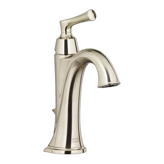
ESTATE
®
SINGLE LEVER MONOBLOCK LAVATORY
WITH SPEED CONNECT
Congratulations on purchasing your American Standard faucet
with Speed Connect drain, a feature found only on American
Standard faucets.
Speed Connect
Drain*
®
• Fewer parts, installs in less time.
• Never needs adjustment.
• Guaranteed to seal properly the first time, every time.
*Your new American Standard faucet is designed to work only with the Speed Connect drain.
To ensure that your installation proceeds smoothly-please read these instructions carefully before you begin.
RECOMMENDED TOOLS
1
INSTALL FAUCET
Fig. A.
• Installation with ESCUTCHEON PLATE: Align PINS (1) with holes in FAUCET BASE (2). Fig. A. Apply a light bead of
plumbers putty to underside of ESCUTCHEON (3) if mounting surface is uneven. Place ESCUTCHEON (3) onto sink or
mounting surface. Fig. A. Feed FAUCET SUPPLIES (4), MOUNTING SHANK (5) and DRAIN CABLE ASSEMBLY (6)
through ESCUTCHEON with PUTTY PLATE (3) and mounting hole of lavatory or mounting surface. Fig. A.
Fig. B.
• Installation with SMALL ESCUTCHEON (10): Align PINS (1) with holes in FAUCET BASE (2). Fig. B.
• Feed FAUCET SUPPLIES (4), MOUNTING SHANK (5) and DRAIN CABLE ASSEMBLY (6) through mounting hole of lavatory or
mounting surface. Fig. B.
Fig.C.
• Seat SEAL (9) under the FAUCET BASE (2) when escutcheon is not used.
• Feed FAUCET SUPPLIES (4), MOUNTING SHANK (5) and DRAIN CABLE ASSEMBLY (6) through mounting hole of lavatory or
mounting surface. Fig. C.
• Fig. A., B. & C. Assemble RUBBER WASHER (7), FRICTION WASHER (7A) and thread LOCKNUT (8) onto MOUNTING
SHANK (5) from underside of sink or mounting surface. Fig. B.
• Adjust Faucet so that it is centered. Tighten MOUNTING NUT (8) to complete faucet mounting. Fig. A., B. & C.
Fig. A.
2
HOLES
(FAUCET
BASE)
1
3
5
7
8
Product names listed herein are trademarks of AS America, Inc.
© AS America, Inc. 2016
DRAIN
®
Screwdriver
Turn off hot and cold water
CAUTION
supplies before beginning.
10
HOLES
(FAUCET
PUTTY
IF REQUIRED
4
7A
6
INSTALLATION
INSTRUCTIONS
7722.101
Channel Locks
Fig. B.
2
BASE)
1
5
4
7
7A
8
6
- 1 -
Certified to comply with ANSI A112.18.1M
Adjustable Wrench
Fig. C.
2
9
HOLES
(FAUCET
BASE)
5
4
7
7A
8
6
M965729 Rev. 1.0 (3/16)
Advertisement

Related Manuals for American Standard Estate 7722.101 Series


Summary of Contents for American Standard Estate 7722.101 Series
- Page 1 • Never needs adjustment. • Guaranteed to seal properly the first time, every time. *Your new American Standard faucet is designed to work only with the Speed Connect drain. To ensure that your installation proceeds smoothly-please read these instructions carefully before you begin.
- Page 2 POP-UP DRAIN Fig. A. Fig. B. • Remove CLEAR PLASTIC COVER (1). • Remove CARDBOARD SPACER (2) from under DRAIN DRAIN POP-UP (3). BODY • Tighten TAIL PIECE (4) on DRAIN BODY before installing DRAIN BODY. Fig. B. REMOVE FLANGE Fig.
- Page 3 ATTACH CABLE CONNECTOR Fig. A. Fig. B. • Thread CABLE CONNECTOR (1) clockwise onto DRAIN BODY CONNECTION (2) and hand tighten. Fig. A. • Your new POP-UP DRAIN installation is now complete. Fig. B. Note: Tail piece on pop-up drain is 1-1/4" O.D.
- Page 4 TEST INSTALLED FITTING COLD • With HANDLE (1) in OFF position, turn on WATER SUPPLIES (2) and check all connections for leaks. • Remove AERATOR (3). • Operate HANDLE (1) to flush water lines thoroughly. • Replace AERATOR (3). CHECK DRAIN CONNECTIONS •...
-
Page 5: Cable Adjustment Procedure
Speed Connect Drain ® Troubleshooting Guide If sink does not hold water even though Stopper is in the “down” position: • Follow CABLE ADJUSTMENT PROCEDURE. If Stopper does not raise up fully or sink drains too slowly: • Follow CABLE ADJUSTMENT PROCEDURE. If you need to remove the Stopper: •... - Page 6 STOPPER INSTALLATION PROCEDURE The Stopper can be installed two ways, “Locked” Mode (Stopper cannot be removed) or “Unlock” Mode (Stopper is removable). Locked Mode: • Look at the Plastic Loop at the bottom of the Stopper and notice that the Fig.
- Page 7 ESTATE ® SINGLE LEVER MONOBLOCK LAVATORY WITH SPEED CONNECT DRAIN ® MODEL NUMBER 7722.101 M970058-YYY0A HANDLE KIT M907315-YYY0A COVER M918511-0070A CARTRIDGE SCREWS M952425-YYY0A M951483-0070A DRAIN ASSEMBLY CARTRIDGE M962544-YYY0A STOPPER ASSEMBLY M952430-0070A CABLE ASSEMBLY M962457-YYY0A FLANGE ASSEMBLY M970056-YYY0A M970004-0070A POP-UP ROD AERATOR (1.2 GPM) ASSEMBLY M922872-0070A...