
Related Manuals for Meinberg IMS-LANTIME-M1000


Summary of Contents for Meinberg IMS-LANTIME-M1000
- Page 1 MANUAL IMS - LANTIME M500 Modular Railmount NTP Server 19th March 2020 Meinberg Funkuhren GmbH & Co. KG...
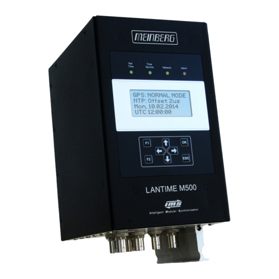
- Page 3 Front view (Frontansicht) IMS - LANTIME M500 DEUTSCH Status LEDs: Ref. Time, Time Service, Network, Alarm LC Display, 4 x 16 Zeichen Funktionstasten: 4-Wege Navigationstasten; F1, F2, OK, ESC ENGLISH Status LEDs: Ref. Time, Time Service, Network, Alarm LC Display, 4 x 16 characters Function buttons: 4-way navigation button;...
- Page 4 Bottom view (Ansicht Unterseite) IMS - LANTIME M500 1 - PWR 2 - CLK 3 - MRI 4 - ESI 5 - CPU 6 - CES DEUTSCH PWR Netzteil (100-240 V AC / 100-200 V DC) GPS Satellitenempfängermodul LAN-CPU RJ45 - 10/100/1000 Base-T SFP - 1000Base-T RJ45 Terminal und USB Chassis Erweiterungs-Slot...
-
Page 5: Table Of Contents
......... . . 5.1.1 Meinberg GPS Antenna/Converter ....... . - Page 6 12.6.6 GNS-UC Clock ......... . . 12.6.7 GNM Clock .
-
Page 7: Imprint
1 Imprint 1 Imprint Meinberg Funkuhren GmbH & Co. KG Lange Wand 9, 31812 Bad Pyrmont / Germany Phone: + 49 (0) 52 81 / 93 09 - 0 Fax: + 49 (0) 52 81 / 93 09 - 230 Internet: https://www.meinbergglobal.com... -
Page 8: Important Safety Information
Meinberg Funkuhren shall not be responsible for any damage arising due to non-observance of these regulations. -
Page 9: Used Symbols
2 Important Safety Information 2.2 Used Symbols The following symbols and pictograms are used in this manual. To illustrate the source of danger, pictograms are used, which can occur in all hazard classes. Symbol Beschreibung / Description IEC 60417-5031 Gleichstrom / Direct current IEC 60417-5032 Wechselstrom / Alternating current IEC 60417-5017... - Page 10 The manuals for a product are included in the scope of delivery of the device on a USB stick. The manuals can also be obtained via the Internet. Enter www.meinbergglobal.com into your browser, then enter the correspond- ing device name in the search field at the top. This manual contains important safety instructions for the installation and operation of the device.
-
Page 11: Security During Installation
2 Important Safety Information 2.3 Security during Installation WARNING! Preparing for Commissioning This built-in unit, has been designed and examined according to the requirements of the standard IEC 60950-1 „Information Technology Equipment - Safety". When the built-in unit is used in a terminal (e.g., housing cabinet), additional requirements according to Standard IEC 60950-1 must be observed and complied with. - Page 12 Connecting Data Cables During a thunderstorm, data transmission lines must not be connected or disconnected (risk of lightning). When wiring the devices, the cables must be connected or disconnected in the order of the arrangement described in the user documentation accompanying the device. Always attach all cables to the plug during connection and removal.
- Page 13 2 Important Safety Information AC Power Supply DC Power Supply The device is a device of protection Outside the assembly group the device must be • • class 1 and may only be connected to a disconnectable from power supply grounded outlet (TN system).
-
Page 14: Protective Conductor- / Ground-Terminal
2.4 Protective Conductor- / Ground-Terminal ATTENTION! In order to ensure safe operation and to meet the requirements of IEC 62368-1, the device must be correctly connected to the protective earth conductor via the protective earth connection terminal. If an external earth connection is provided on the housing, it must be connected to the equipotential bonding rail (grounding rail). -
Page 15: Safety During Operation
2 Important Safety Information 2.5 Safety during Operation WARNING! Avoiding Short-Circuits Make sure not to get any objects or liquids inside the unit. Electric shock or short circuit could result. Ventilation Slots Make sure that the ventilation slots are not covered or dusty, as there is a danger of overheating during operation. -
Page 16: Safety During Maintenance
2.6 Safety during Maintenance WARNING! When you are expanding the device, use only device parts that are approved for the system. Non-observance may result in injury to the EMC or safety standards and cause malfunction of the device. If device parts, which are released for the system, are extended or removed there may be a risk of injury in the area of the hands, due to the pull-out forces (approx. -
Page 17: Cleaning And Care
2 Important Safety Information 2.8 Cleaning and Care ATTENTION! Do not wet clean the appliance! Penetrating water can cause considerable dangers to the user (e.g., electric shock). Liquid can destroy the electronics of the device! Liquid penetrates into the housing of the device and can cause a short circuit of the electronics. -
Page 18: Return Of Electrical And Electronic Equipment
Return and Collection Systems For returning your old equipment, please use the country-specific return and collection systems available to you or contact Meinberg. The withdrawal may be refused in the case of waste equipment which presents a risk to human health or safety due to contamination during use. -
Page 19: The Modular System Lantime
3 The Modular System LANTIME 3 The Modular System LANTIME LANTIME is a set of equipment composed of a reference clock GNSS, a single-board computer (LAN-CPU) with integrated network card, and a power supply unit, all installed in a metal desktop case and ready to operate. The interfaces provided by LANTIME are accessible via connectors in the rear panel of the case. -
Page 20: Network Timeserver With Gnss Synchronized Time Base
4 Network Timeserver with GNSS synchronized time base The LANTIME (Local Area Network Time Server) provides a high precision time base to a TCP/IP network (Stratum-1-Server). The NTP (Network Time Protocol) is used to synchronize all NTP clients with the ref- erence. -
Page 21: Mounting The Antenna
Since the satellite orbits are located between latitudes 55 North and 55 South, this allows for the best possible reception. Meinberg provides their own GPS receivers which operate with an antenna/converter unit and thus allow for very long antenna cables, but some devices also include GNSS receivers which support other satellite sys- tems like GLONASS, or Galileo in addition to GPS. -
Page 22: Meinberg Gps Antenna/Converter
5.1.1 Meinberg GPS Antenna/Converter 5.1.1.1 Introduction The Meinberg GPS antenna/converter unit combines a standard GPS patch antenna with a frequency converter which translates the original 1.5 GHz signal received from the GPS satellites to an intermediate frequency, so a standard coaxial cable type like RG58 can be used for antenna cable lengths up to 300 meters (1000 ft). If a low-loss cable type like RG213 is used then even 700 meters (2300 ft) between receiver and antenna are possible without requirement for an additional amplifier. - Page 23 GPS Antenna N-Norm female N-Norm male Cable Slot N-Norm male N-Norm female as short as possible N-Norm female Meinberg GPS N-Norm male N-Norm male female Ground lead to PE rail or BNC male female (Protective Earth) Cable ca. 1,5 mm Ø...
- Page 24 Note: If the antenna cable is assembled locally instead of using a cable shipped with the GPS receiver it has to be made sure that the connectors have been soldered and assembled properly, and that there is no short-circuit in the cable or in one of the connectors. Otherwise GPS reception may be degraded, or the GPS receiver can even be damaged.
-
Page 25: General Gnss Antennae
Some Meinberg devices use alternate GNSS receivers which support other satellite systems like GLONASS, Galileo or BeiDou, in addition to GPS. These receivers can’t be operated directly with the standard Meinberg antenna/converter unit described in chapter "Meinberg GPS Receiver", so they require a different kind of antenna. - Page 26 WARNING! Antenna mounting without effective anti-fall protection Danger to life due to fall! - Pay attention to effective working safety when installing antennas! - Never work without an effective anti-fall equipment! WARNING! Working on the antenna system during thunderstorms Danger to life due to electrical shock! - Do not carry out any work on the antenna system or the antenna cable if there is a risk of a lightning strike.
- Page 27 5 Mounting the Antenna 5.1.2.2 GNSS Antenna for Mobile Applications The RV-76G is an active GNSS antenna which can receive the signals of the GPS, GLONASS, and Galileo satellite systems. It operates with a 5V DC supply voltage provided by the receiver, and should be preferred for mobile applications.
-
Page 28: Powering Up A Gnss Receiver
5.1.3 Powering up a GNSS Receiver If both the antenna and the power supply have been connected the system is ready to operate. Depending on the type of oscillator installed in the receiver it takes about 10 seconds (OCXO-LQ) until 3 minutes (OCXO-MQ / HQ) until the oscillator has warmed up and reached the required frequency accuracy. -
Page 29: Long Wave Signal Reception
DC current, an extra power supply is required in this case at the location of the antenna. Longwave receiver equipment from Meinberg has specifically been designed for Meinberg devices and is not necessarily compatible with receivers from 3rd party manufacturers. -
Page 30: Mounting And Installation Of A Longwave Antenna
Antenna aligned to the transmitter N-Norm female N-Norm male Cable slot N-Norm male N-Norm female as short as possible N-Norm female Meinberg DCF N-Norm male N-Norm male female Ground lead to PE rail (Protective Earth) or BNC male female Cable ca. 1,5 mm Ø... - Page 31 5 Mounting the Antenna The antenna has to be aligned horizontally in longitudinal direction to the transmitter, i.e. in direction to Mainflingen near Frankfurt / Main in case of DCF77, or in direction to the location of the MSF or WWVB receiver accordingly.
-
Page 32: Dcf77 / Pzf Receiver
For further detailed clock configuration, please refer to the Chapter ??". 5.3 Cable Types Antenna Type Cable Type Maximum Cable Length Meinberg GPS Antenna RG58 300 m / 1000 ft Meinberg GPS Antenna RG213 700 m / 2300 ft... -
Page 33: Quick Start
6 Quick Start 6 Quick Start When the unit is switched on, the following message appears on the display, which counts up a number of points during the boot process: LANTIME OS7 [7.00.006-STD] HW Init ... The NTP time server is then ready for operation and the display switches to the main menu where some important status information will be displayed: MRS: Sync to GNS NTP: Offs. -
Page 34: Booting The Gnss Receiver
7 Booting the GNSS receiver If both the antenna and the power supply have been connected, the system is ready to operate. About 2 minutes after power-up the receiver’s oscillator has warmed up and operates with the required accuracy. If the receiver finds valid almanac and ephemeris data in its battery buffered memory and the receiver’s position has not changed significantly since its last operation, the receiver can determine which satellites are presently in view. -
Page 35: Booting The Single Board Computer
8 Booting the Single Board Computer 8 Booting the Single Board Computer The LINUX operating system is loaded from a packed file on the flash disk of the single board computer to a RAM disk. All files of the flash disk are stored in the RAM disk after booting. This guarantees that the file system is in a defined condition after restart. -
Page 36: Configuration User Interface
9 Configuration User Interface There are several ways to configure the LANTIME parameters: Command Line Interface (CLI) via TELNET Command Line Interface via SSH Command Line Interface via serial terminal in front panel (38400/8N1/VT100) HTTP Interface Secure HTTP Interface (HTTPS) Front panel LCD/VFD Interface (except LANTIME M100 and IMS S-Chassis variants) SNMP Management In order to be able to configure the time server via the web interface or a telnet/SSH connection, an IP... -
Page 37: The Menues In Detail
10 The Menues in Detail 10 The Menues in Detail 10.1 Root Menu The root menu is shown when the receiver has com- pleted initialization after power-up. With the four arrow buttons and the buttons "OK", "ESC", "F1" and "F2" the navigation and setting of parameters can be ma-naged. - Page 38 When pressing "F1" from main menu a short description for menu navigation will be displayed: Use -> and <- to select different main menus. Use ^ and v to enter When pressing the "OK" button from main menu the version of the LANTIME software, the NTP and the LINUX kernel version will be displayed.
-
Page 39: Lantime Web Interface
11 LANTIME Web Interface 11 LANTIME Web Interface The LANTIME offers two different options for configuration and status management: An extensive and powerful web interface and SNMP. In order to use the SNMP features of your LANTIME, you need special software like management systems or SNMP clients. - Page 40 If you try a secure connection via HTTPS, then your WEB Browser generates an alarm message. You have to accept the HTTPS certificate which the LANTIME provides to you. Modification of this certificate is possible during the first session (see chapter The Web Interface - Security - HTTPS Certificate). After entering the right password, the main menu page shows up.
-
Page 41: Attachment: Technical Information
12 Attachment: Technical Information 12 Attachment: Technical Information 12.1 Technical Specifications LANTIME / IMS-M500 Housing: Metal desktop case, DIN Mounting Rail 117,5 mm (4.63 inch) x 193,2 mm (7.61 inch) x 159,8 mm (6.29 inch) / W x H x D with module handles and connectors 117,5 mm (4.63 inch) x 227,3 mm (8.95 inch) x 159,8 mm (6.29 inch) / W x H x D Humidity:... - Page 42 Variant: 100-240 V AC / 100-200 V DC 1 2 3 4 5 1: VCC - 2: not connected 3: GND (Ground) 4: not connected 100-200 V 5: VCC + 100-240 V / 50-60Hz Variant: 20-60 V DC 1 2 3 4 5 not connected VCC - GND (Ground)
-
Page 43: Available Modules And Connectors
12 Attachment: Technical Information 12.2 Available Modules and Connectors Name Type Signal Cable ——————————————————————————————————————————– Front Connectors Terminal 9pin. D-SUB male RS-232 shielded data line USB Port USB Stick Rear Connectors Power supply 5pin. DFK male 100-240 V AC (50-60 Hz) 5pin. -
Page 44: Terminal (Console)
12.3 TERMINAL (Console) To connect a serial terminal (according to the device model), use the 9pin RS-232 D-Sub connector in the front panel or the RJ45 connector of the LAN-CPU. Via the serial terminal connection it is possible to con- figure parameters with a command line interface. -
Page 45: Replacement Or Installation Of A Hot-Pluggable Ims Module
12 Attachment: Technical Information 12.5 Replacement or Installation of a Hot-pluggable IMS Module If the system is supplied with an antenna and antenna cable, it is advisable to first mount the antenna in a suitable location (see chapter Antenna Mounting) and lay the antenna cable. Please use a Torx screwdriver (T8 x 60) for removal and installation of the module. -
Page 46: Important Hints For Hot-Pluggable Ims Modules
12.5.1 Important Hints for hot-pluggable IMS Modules The following points should be strictly observed when replacing IMS modules during operation. Not all IMS modules are fully hot-pluggable. Of course, it is not possible to replace a power supply unit of a non-redundant system without first having installed a second power source in operational mode. -
Page 47: Ims Module Options
12 Attachment: Technical Information 12.6 IMS Module Options 12.6.1 Power Supply 100-240 V AC / 100-200 V DC Connector Type: 5-pol. DFK Pin Assignment: 1: N/- AD10 2: not connected 3: PE (Protective Earth) 4: not connected 5: L/+ 100-240 V Input Parameter = 90 -265 V... -
Page 48: Power Supply 20-60 V Dc
12.6.2 Power Supply 20-60 V DC Connector: 5pin DFK Pin Assignment: not connected DC20 PE (Protective Earth) not connected Input Parameter = 24-48 = 20-60 ——————————————————————————– = 2.1 A Nominal voltage range: = 24-48 V Maximum voltage range: = 20-60 V Nominal current: = 2.1 A Output Parameter... -
Page 49: Power Supply 10-36 V Dc
12 Attachment: Technical Information 12.6.3 Power Supply 10-36 V DC Connector: 5pin DFK Pin Assignment: not connected DC10 PE (Protective Earth) not connected Input Parameter = 24 = 10-36 ——————————————————————————– = 2.5 A Nominal voltage: = 24 V Maximum voltage range: = 10-36 V Nominal current: = 2.5 A... -
Page 50: Gps Clock
12.6.4 GPS Clock Receiver: 12 channel GPS C/A-code receiver Accuracy Depends on oscillator option: of pulse outputs: < +-100 ns (TCXO, OCXO LQ) < +-50 ns (OCXO-SQ, -MQ, -HQ, -DHQ) Antenna Cable: shielded coax Cable Length: max. 300 m to RG58, max. - Page 51 Pin 1: PPS Pin 2: String * * The following timestrings (time telegrams) can be used: NMEA RMC NMEA ZDA Meinberg Standard Uni Erlangen Pin Assignment of the optional XHE-SPI Connectors: A1: PPS In A2: PPS Out Pin 1: SCL_Out (SPI Clock)
-
Page 52: Gnss Clock
12.6.5 GNSS Clock Type of receiver: GPS / GLONASS / Galileo / Beidou receiver Number of channels: 72 Frequency band: GNSS L1 1575.42 +- 10 MHz / 1602-1615 MHz Accuracy of Pulses: Dependant on oscillator option < +-100nsec (TCXO, OCXO-LQ) <... - Page 53 Pin 1: PPS Pin 2: String * * The following timestrings (time telegrams) can be used: NMEA RMC NMEA ZDA Meinberg Standard Uni Erlangen Pin Assignment of the optional XHE-SPI Connectors: A1: PPS In A2: PPS Out Pin 1: SCL_Out (SPI Clock)
-
Page 54: Gns-Uc Clock
12.6.6 GNS-UC Clock GNSS receiver with UpConverter for operation on a standard Meinberg GPS antenna/converter unit. Type of receiver: GPS / Galileo receiver Number of channels: 72 GPS: L1C/A Galileo: E1B/C 181-UC 181-UC Accuracy of Pulses: Dependant on oscillator option <... - Page 55 Pin 1: PPS Pin 2: String * * The following timestrings (time telegrams) can be used: NMEA RMC NMEA ZDA Meinberg Standard Uni Erlangen Pin Assignment of the optional XHE-SPI Connectors: A1: PPS In A2: PPS Out Pin 1: SCL_Out (SPI Clock)
-
Page 56: Gnm Clock
12.6.7 GNM Clock Receiver Type 184-channel GPS, GLONASS, Galileo, Beidou Frequency Band: GPS: L1C/A (1575.42 MHz) L2C (1227.60 MHz) GLONASS: L1OF (1602 MHz + k*562.5 kHz L2OF (1246 MHz + k*437.5 kHz k = –7,..., 5, 6 Galileo: E1-B/C (1575.42 MHz) E5b (1207.140 MHz) Beidou: B1I (1561.098 MHz) B2I (1207.140 MHz) - Page 57 Pin 1: PPS Pin 2: String * * The following timestrings (time telegrams) can be used: NMEA RMC NMEA ZDA Meinberg Standard Uni Erlangen Pin Assignment of the optional XHE-SPI Connectors: A1: PPS In A2: PPS Out Pin 1: SCL_Out (SPI Clock)
-
Page 58: Pzf Clock
12.6.8 PZF Clock Receiver: High accuracy DCF77 correlation receiver Two seperate receiver channels for signal conversion and best aquisition and tracking of the DCF77 signal (AM + PZF). Synchronization Time: 2-3 minutes after correct DCF77 signal reception Frequency Outputs: Accuracy depends on oscillator (standard: OCXO-SQ) Pulse Outputs: Pulse per second (PPS) and pulse per minute (PPM). -
Page 59: Tcr Clock - Time Code Reader And Generator
12 Attachment: Technical Information 12.6.9 TCR Clock - Time Code Reader and Generator The IMS - TCR180 serves to decode and generate mod- ulated (AM) and unmodulated (DC Level Shift) IRIG- A/B/G, AFNOR, C37.118 or IEEE1344 time codes. AM-codes are transmitted by modulating the ampli- tude of a sine wave carrier, unmodulated codes by variation of the width of pulses. - Page 60 Generator: The generator of TCR180 is capable of producing time codes in IRIG-A/B/G, AFNOR, C37.118 or IEEE1344 format. The codes are available as modulated (3 V /1 V into 50 ) and unmodulated (DC Level Shift) signals (TTL into 50 and RS-422).
- Page 61 7E2, 8N1, 8N2, 8E1, 7N2, 7E1, 801 Mode of operation: string per second string per minute string on request Time telegram: Meinberg Standard, Uni Erlangen, SAT, Meinberg Capture, ION, Computime, SPA, RACAL Capture Inputs Triggered by falling TTL slope Pulse repetition time: 1.5 msec min.
- Page 62 Pin 5: GND Synchronization with PPS + String*: Pin 1: PPS Pin 2: String * * The following timestrings (time telegrams) can be used: NMEA RMC NMEA ZDA Meinberg Standard Uni Erlangen Date: 19th March 2020 IMS - LANTIME M500...
-
Page 63: Lan-Cpu
12 Attachment: Technical Information 12.6.10 LAN-CPU As the central management and control element, the CPU module in an LANTIME system is responsible for management, configuration and alarm notifications. It additionally provides NTP and SNTP services on its network interface. Technical specifications IMS LAN CPU C05F1 Processor: AMD Geode LX 800 Processor,... - Page 64 Status LEDs: —————————————————————————– LAN 0 LED - Connect, Activity and Speed of the network connection R (Receiver) green: the reference clock (e.g. build-in GNSS) provides a valid time red: the reference clock does not provide a valid time T (Time Service) green: NTP is synchronized to the reference clock, e.g.
-
Page 65: Reference Input Modules (Mri, Esi)
12 Attachment: Technical Information 12.6.11 Reference Input Modules (MRI, ESI) 12.6.11.1 MRI - Standard Reference Input Signals If an application requires to use external synchronization sources instead of radio/GNSS signals, an MRI card enables the installed clock module to synchronize to 1PPS, 10 MHz, DCLS and AM time codes (IRIG B, AFNOR, IEEE1344 or C37.118). - Page 66 Status Indicators LED St: MRI status LED In: Status of the backplane’s reference signals LED A: Status of the input signals (TC-AM/DCLS) at the board LED B: Status of the input signals (10 MHz/PPS) at the board Initialisation: LED St: blue until USB is configured LED In - LED B: off...
- Page 67 12 Attachment: Technical Information 12.6.11.2 MRI Configuration via the Web Interface The MRI module is a card for fixed (none configurable) input signals (Time Code AM / DCLS, 10 MHz and PPS). The provided input signals can be monitored and selected in the "Clock" menu after initializing. Menu MRS State: Displays the available input signals MRS settings: selection and prioritization of existing input sources IMS - LANTIME M500...
- Page 68 12.6.11.3 ESI - Telecom Synchronisation References Enhanced Synchronisation Inputs Reference Inputs: PPS and variable frequencies unframed, 1 kHz - 20 MHz 2,048 Mbit/s / 1,544 Mbit/s - E1/T1 framed Input 1 1PPS (BNC female connector) TTL, pulse duration 5 s, active high Input 2 1 kHz - 20 MHz (BNC female connector) sine (400 mV...
- Page 69 12 Attachment: Technical Information Pin assignment of the RJ-45 jacks (input 3 + 4) IMS - LANTIME M500 Date: 19th March 2020...
- Page 70 12.6.11.4 ESI Configuration via Web Interface ESI – External Synchronization Input Menu "IO Config -> Input Configuration -> ESI - External Synchronization Interface" The ESI (External Synchronization Input) card is capable of adding additional synchronization sources to an IMS system. It accepts E1 and T1 sources as a Bitstream (2.048 MBit/s/1.544 Mbit/s, supporting SSM/BOC). It also handles configurable frequencies (1 kHz - 20 MHz) and 1PPS pulse synchronization source, if re- quired.
- Page 71 12 Attachment: Technical Information Input 2: accepts as input signal configurable frequencies from 1 kHz to 20 MHz. Type: Freq. In Frequency Fill in a configurable frequency, 10 MHz is set as default value. Maximum Slip n Cycles A discontinuity of an integer number of cycles in the measured carrier phase resulting from a temporary loss of input signal.
- Page 72 Input 4: As fixed frequency you can choose between E1 framed or T1 framed Minimum Quality Levels: Synchronization Status Message (SSM) in accordance with ITU G.704-1998 standard includes 4 bit long SSM quality messages received via incoming E1 framed signal. The clock source quality levels according to G.704- 1998 are as follows: QL-STU/UKN Quality unknown, existing synchronization network...
-
Page 73: Cpe And Bpe Output Modules (Frontend - Backend, Eurocard)
12 Attachment: Technical Information 12.6.12 CPE and BPE Output Modules (Frontend - Backend, Eurocard) Configurable Port Expander / Backplane Port Expander The standard output signals like pulses (1PPS, 1PPM and freely programmable pulses) and frequencies (10MHz, 2.048MHz, frequency synthesizer 1kHz-10MHz) are provided by two versatile I/O cards named BPE and CPE. Both of these two modules have been designed to cover a wide range of interface and signal/protocol require- ments. - Page 74 12.6.12.1 BPE - Backplane Port Expander Please Note: In principle, it should be noted that the signals that are provided via a BPE at the various connectors are always generated by the upstream clock and spread via the backplane of the system. In opposite to the CPE, the signals are not generated by the module and therefore the outputs can only be set via the receiver.
- Page 75 12 Attachment: Technical Information 12.6.12.2 Available BPE Modules BPE Type Connectors Signals Size BPE-1040 4 x BNC female Out 1 - Out 4: TC AM BPE-1060 4 x BNC female Out 1 - Out 4: DCF77 SIM BPE-2000 4 x BNC female Out 1: PPS, Out 2: 10 MHz Out 3: TC DCLS, Out 4: TC AM BPE-2001...
- Page 76 BPE Type Connectors Signals Size BPE-2110 8 x BNC female Out 1 - Out 8: PPS BPE-2120 8 x BNC female Out 1 - Out 8: 10 MHz BPE-2180 8 x BNC female Out 1 - Out 8: 2048 kHz BPE-2500 4 x 2pin DFK Out 1 - Out 4: Progr.
- Page 77 12 Attachment: Technical Information BPE Type Connectors Signals Size BPE-4043 4 x RJ45 RS422, Pin_3 T-, Pin_6 T+ BPE-6042 2 x DMC 16-pin 10 x PPO - RS-422 galvanic isolated Fiber-Optical Outputs BPE-5000 4 x FST PPS, 10 MHz, TC-DCLS, 2048 kHz FO Multimode BPE-5010 4 x FST...
- Page 78 12.6.12.3 Configuring an BPE expansion card via the Web Interface A simple BPE expansion card usually gets its signals directly from the internal backplane of the system. The output signals of the card are pre-configured according to customer requirements. If an output signal has to be changed, this must be done via the pre-connected receiver - in the menu "Clock Switch Card"...
- Page 79 12 Attachment: Technical Information 12.6.12.4 BPE-8000 - Switchable Backplane Port Expander Output Signals: adjustable via the web interface (TTL or Fiber Optical): PPS, 10 MHz, 2048 kHz, TC-DCLS, Progr. Pulses or fixed: 2048 kHz (ITU G.703-15), TC-AM Power Requirements: 5 V +-5%, 150 mA / BNC 5 V +-5%, 150 mA / FO Status Indicators LED St:...
- Page 80 Available BPE-8000 Models 8000 8100 8200 8300 8400 8500 8600 8700 4 x TTL 4 x FO MMF 2 x FO MMF 4 x FO SMF 2 x FO SMF 2 x FO MMF 4 x 2.048MHz 3 x TTL via BNC via ST via ST...
- Page 81 12.6.12.5 Configuring an BPE-8000 expansion card via the Web Interface Via the web interface or the Meinberg Device Manager (MDU), the following signals can be distributed to the BNC connectors (TTL) or fiber optical connectors (ST) according to your choice: PPS, 10MHz, Time Code DCLS, 2048 kHz and programmable pulse outputs PP 1 - PP 4 of the upstream reference source.
- Page 82 12.6.12.6 BPE-1060 4 x SIM77 Backplane Port Expander (Frontend / Backend) Output Signals: fixed: Out 1 - Out 4: SIM77 (DCF77 compatible Signal) via isolated female BNC connectors (-60dBm) Power Requirements: 5 V +-5%, 150 mA / BNC 5 V +-5%, 150 mA / FO Status Indicators LED St: BPE status...
- Page 83 12 Attachment: Technical Information SIM77 - amplitude-modulated time signal The amplitude-modulated time signal is compatible with the DCF77 signal, transmitted by the German long- wave transmitter. The SIM77 signal is provided via four DC insulated BNC sockets. Note: Important configuration parameters must be observed when using the BPE-1060 module in an IMS system. In the Web Interface, in the menu "Clock Programmable pulse outputs Prog.
- Page 84 In the example below, several time zones are entered with the changeover rule for summer and winter time. Please note, that these settings will also affect other output modules which provide the programmable pulse output "Prog. Out 1". Date: 19th March 2020 IMS - LANTIME M500...
- Page 85 12 Attachment: Technical Information 12.6.12.7 CPE - Configurable Port Expander (Frontend) CPE (Configurable Port Expander) The CPE is a configurable IO card that can autonomously generate additional output signals from the inte- grated system clock. This module consists of a half-size standard controller card (back-end) and a dockable port expander card (front-end), like this a wide variety of available programmable output signals and physical connections are possible, including various electrical and optical interfaces.
- Page 86 12.6.12.8 Available CPE Modules BPE Type Connectors Signals Size CPE-1000 4 x BNC female prog. pulses CPE-1002 1 x D-SUB9 Time Telegram, RS232 2 x BNC female Capture Inputs CPE-1040 4 x BNC female TC AM / BNC CPE-1050 4 x BNC female 3 x progr.
- Page 87 12 Attachment: Technical Information 12.6.12.9 CPE-3000: Programmable Outputs via serial Interface The CPE-3000 module has two serial ports (COM A and B) for various output signals. The two interfaces can also be used for communication with other devices. The possible pin assignments and module types are listed below: CPE-3000 CPE-3010 CPE-3020...
- Page 88 The module CPE-4020 has two interfaces with RJ45-connector (COM A and B). These provide Time String + PPS with RS422 level. The following configurations must be performed to correctly output the signals. Baud Rate 19200 Framing 4020 String Type Meinberg GPS Mode per second (PPS) Pin assignment Pin 3: TXD_P, serial interf. transmit pos. Pin 5:...
- Page 89 12 Attachment: Technical Information 12.6.12.11 CPE-4020 Configuration via Web Interface If the CPE-4020 operates in an IMS system, the output configuration can easily be done via the web interface then. With the "Common" tab the time zone with the corresponding offset can be selected. Configuration: CPE-4020 In the "IO Config"...
- Page 90 Figure: Selection of programmable pulse outputs Date: 19th March 2020 IMS - LANTIME M500...
- Page 91 12 Attachment: Technical Information 12.6.12.12 CPE - Configuration via Web Interface If the CPE operates in an IMS system, the output configuration can easily be done via the web interface then. With the "Common" tab the time zone with the corresponding offset can be selected. CPE Configuration In the "IO Config"...
- Page 92 Figure: Menu Tab "IRIG Out" Selection of the IRIG code (IRIG DCLS only) Figure: Menu Tab "Prog. Out" Selection of the signal option for the programmable pulse output (PPO) The following programmable pulse outputs can be selected: Idle (not in use) Timer (3 switching-times On - Off) Single Shot...
-
Page 93: Lne-Gbe: Network Expansion With Gigabit Support And Sfp Option
12 Attachment: Technical Information 12.6.13 LNE-GbE: Network Expansion with Gigabit Support and SFP Option Link speed: 10/100/1000 Mbita Connector Type: 8P8C (RJ45) Cable: CAT 5.0 Duplex Modes: Half/Full/Autonegotiaton LED Indicators LED St: Init lights blue during initialisation LED In - LED B: Shows the state of the four LAN ports after initialisation green normal operation defective LAN port... - Page 94 Recommended and tested Transceivers from other Vendors Mode Vendor/Type Distance ———————————————————————————————————————– MULTI MODE: AVAGO AFBR-5710PZ 550 m FINISAR FTLF8524P3BNL 500 m SINGLE MODE: AVAGO AFCT-5710PZ 10 km FINISAR FTLF1318P3BTL 10 km SMARTOPTICS SO-SFP-L120D-C63 80 km RJ-45: AVAGO ABCU-5740RZ 100 m FINISAR FCLF8521P2BTL 100 m LAN interface alignment with several LNE modules in operation:...
- Page 95 12 Attachment: Technical Information 12.6.13.1 LNE-GBE Configuration via the Web Interface If the LNE-GBE operates in an LANTIME system, all network settings can be configured via the web interface then. Physical Network Configuration Net Link Mode: The network interfaces LAN1 - LAN4 (LNE-GBE) can be used in 1000 MBIT HALF / FULL duplex mode.
- Page 96 Menu Interfaces IPv4: Manually adjustment of all important parameters such as TCP / IP address, subnet mask and gateway. The DHCP client can also be activated here for automatic network configurations. Misc: With the tab Misc the virtual interface can be assigned to a physical interface. VLAN: With VLAN, this function can be enabled and configured.
- Page 97 12 Attachment: Technical Information 12.6.13.2 Adding / Removing an LANTIME Network Extension LNE An LNE module can be installed in each MRI/ESI or IO Slot of a LANTIME IMS device. Adding a LANTIME Network Extension After installing the LNE module, please start the web interface. In the menu "System Services and Functions"...
-
Page 98: Hps-100: Ptp / Synce / Hardware Ntp Interface
12.6.14 HPS-100: PTP / SyncE / Hardware NTP Interface IEEE 1588 v2 compatible Profiles: IEEE 1588v2 Default Profile IEEE 1588v1 (option) Enterprise Profile IEC 61850-9-3 Power Profile IEEE C.37.238-2011 Power Profile IEEE C.37.238-2017 Power Profile ITU-T G.8265.1 Telecom Frequency Profile ITU-T G.8275.1 Telecom Phase / Time Profile (full timing support) ITU-T G.8275.2 Telecom Phase / Time Profile (partial timing support) SMPTE ST 2059-2 Broadcast Profile... - Page 99 12 Attachment: Technical Information LED Indicators LED St: Init lights blue during initialisation, off in normal operation mode LED In: Error - TSU does not work correctly, PTP services stopped yellow No link, but initialized green link up stopped LED A - LED B: Shows the current State of the TSU yellow - yellow Listening green - off...
- Page 100 A detailed configuration guide you will find in the corresponding firmware manual of the system. See chapter "The Web Interface -> Configuration: PTP V2". Figure: Webinterface - PTP Menu Global Configuration Date: 19th March 2020 IMS - LANTIME M500...
-
Page 101: Tsu V3: Ieee-1588 Time Stamp Unit
12 Attachment: Technical Information 12.6.15 TSU V3: IEEE-1588 Time Stamp Unit TSU v3 (IEEE 1588 v2 compatible) Profiles: IEEE 1588v2 Default Profile IEEE C.37.238 Power Profile ITU-T G.8265.1 Telecom Frequency Profile ITU-T G.8275.1 Telecom Phase/Time Profile SMPTE ST 2059-2 Broadcast Profile PTP Modes: Multicast Layer 2 (IEEE 802.3) Multicast/Unicast Layer 3 (UDP IPv4/IPv6) - Page 102 LED Indicators LED St: Init lights blue during initialisation, off in normal operation mode LED In: Error - TSU does not work correctly, PTP services stopped yellow No link, but initialized green link up stopped LED A - LED B: Shows the current State of the TSU yellow - yellow Listening green - off...
-
Page 103: Ims Pio: Pps Or 10 Mhz I/O Module
12 Attachment: Technical Information 12.6.16 IMS PIO: PPS or 10 MHz I/O Module Technical Specifications: Connectors: 4 x BNC female, isolated, individually switchable as input or output St In P C Signal Options: PPS or 10 MHz Status Indicators LED St: PIO status LED In: Status of the backplane’s output signals... - Page 104 12.6.16.1 PIO - Configuration via the Web Interface The PIO module is pre-configured by a jumper. The default configuration of all ports is PPS (Pulse Per Second). If this pre-configuration needs to be changed to 10 MHz, the card must be removed and the jumper position adjusted.
-
Page 105: Liu - Line Interface Unit
12 Attachment: Technical Information 12.6.17 LIU - Line Interface Unit Input signal: 2.048 MHz reference clock, TTL level Clock: T1 - 1.544 MHz A4004 E1 - 2.048 MHz Power T1 E1 BITS: T1 - 1.544 MBit/s E1 - 2.048 MBit/s Outputs: balanced - RJ45 jack - 120 (Clock) - Page 106 12.6.17.1 IMS-LIU Telecom Output Signals The board LIU (Line Interface Unit) was designed to convert the GNSS-locked standard frequency of a pre- connected Meinberg satellite controlled clock (GPS or GPS/GLONASS/Galileo/BeiDou) into several timing signals that can be used for various synchronization or measurement tasks.
- Page 107 12 Attachment: Technical Information 12.6.17.2 Block Diagram LIU The following block diagram illustrates the functional principle of the board LIU: LIU V3 isolation framed outputs isolation T1.403/G703-9, USB/IMS balanced (or unbalanced), isolation interface 1.544 Mbps or 2.048 Mbps isolation isolation RS232 interface isolation...
- Page 108 12.6.17.3 Telecom Signals These signals can be devided into two groups: the "clock" outputs and the "framed" outputs, that are provided by a framer and line interface device on the board LIU. All clock signals needed for generation of the ‘telecom outputs’...
- Page 109 12 Attachment: Technical Information 12.6.17.4 Pulse templates The following pulse templates are required by ANSI (T1-mode) and CCITT (E1-mode) for output signals in telecom applications. The board LIU meets these recommendations. T1 (T.403): E1 (G.703): IMS - LANTIME M500 Date: 19th March 2020...
- Page 110 12.6.17.5 LIU - Configuration Samples The Line Interface Unit (LIU) is available in two different sizes and different output / connector options. All outputs of a module can be operate in either the E1 or T1 in mode. Signal output settings can be done during operation via the web interface.
- Page 111 12 Attachment: Technical Information LIU Model Size Signal (bal./unbal.) Connectors ———————————————————————————————————————– LIU-A0040 Clock (4/0) 4 x RJ45 LIU-A0004 Clock (0/4) 4 x BNC LIU-A2020 BITS (2/0) 2 x RJ45 Clock (2/0) 2 x RJ45 LIU-A2002 BITS (2/0) 2 x RJ45 Clock (0/2) 2 x BNC LIU-A0400...
- Page 112 12.6.17.7 LIU Configuration via Web Interface Output Configuration of a LIU module (Line Interface Unit): In this menu one can select between E1 or T1 mode for the LIU outputs. The selected mode is the same for all outputs. T1 or E1? T1 is a digital carrier signal that transmits the DS - 1 signal.
-
Page 113: Mhz Sinus Output Module
12 Attachment: Technical Information 12.6.18 LNO - 10 MHz Sinus Output Module The LNO180 is a 10 MHz generator card, which provides sine signals with low phase noise to 4 external outputs. The card has a microprocessor system, which monitors the output signals and generates status signals for the upper-level management system accordingly. - Page 114 LED Status Indicators: All LEDs red Outputs disabled PLL not locked, OCXO in warm up phase 10 MHz reference not available Quality of the reference signal is not sufficient All LEDs green: Normal operation, outputs activated Associated LED red: defect output or short circuit during normal operation Date: 19th March 2020 IMS - LANTIME M500...
-
Page 115: Fdm - Frequency Deviation Monitoring
12 Attachment: Technical Information 12.6.19 FDM - Frequency Deviation Monitoring The module FDM180 was designed to calculate and monitor the frequency and its deviation in 50/60Hz power line networks. A preconnected reference is necessary that provides a serial time string and a PPS (pulse per second). The accuracy of the measurements is derived from these signals. - Page 116 Input signal: Serial time string, PPS mains frequency, 70 - 270 V AC, 50Hz or 60Hz Interface: Two asynchronous serial RS-232 ports, COM0 and COM1 Baudrate: 1200, 2400, 4800, 9600, 19200, 38400, 57600, 115200 Baud Framing: 7N2, 7E1, 7E2, 8N1, 8N2, 8E1, 7O2 output and average: once per second or 100ms Output string: The frequency, frequency deviation, reference time, power line time...
-
Page 117: Rel1000: Error Relay Module
12 Attachment: Technical Information 12.6.20 REL1000: Error Relay Module The REL1000 error relay module can be switched by various operating states (e.g.: Clock Not Sync). If the internal hardware clock is running synchronous to the source, the relay is switched to NO (Normaly Open) mode. - Page 118 State of LED Indicators: Initialisation Phase: blue off off off Boot Phase: blue 1s red, 1s yellow, 1s green, 1s off 1s red, 1s yellow, 1s green, 1s off 1s red, 1s yellow, 1s green, 1s off Normal Operation Mode: green (Status) green, red in case of error (Clock 1) green, red in case of error (Clock 2)
- Page 119 12 Attachment: Technical Information 12.6.20.1 Configuration of the REL1000 via the Web Interface The relays A + C of the REL1000 module can be switched via notifications events. If the jumpers and hardware configuration are set accordingly, a checkbox can be activated in the web interface menu "Notification tification Events"...
-
Page 120: Scg-U: Studio Clock Generator
12.6.21 SCG-U: Studio Clock Generator Add-On module for generating various audio frequen- cies (12 kHz, 32 kHz, 44.1 kHz, 48 kHz, 64 kHz, 88.2 kHz and 96 kHz), with only one 10 MHz input clock, for studio applications. The SCG Module provides four outputs with different frequencies. - Page 121 12 Attachment: Technical Information 12.6.21.1 SCG-U: Configuration via Web Interface (Firmware version 6.19 or later) If the SCG-U operates in an IMS system, the module can be easily configured via the web interface then. Configuration Sample: SCG Output 3 In the "IO Configuration" menu each output frequency can be adjusted seperately. In the figure above the fol- lowing value is set: Frequency Out 3 = Base Frequency * Scale Frequency Out 3 = 44,1 kHz * 1/4...
-
Page 122: Scg-B: Studio Clock Generator Balanced
12.6.22 SCG-B: Studio Clock Generator Balanced The IMS-M500 is an additional card for generating "Digi-tal Audio Reference Signals" for studio applica- tions. The 25pin D-Sub female connector provides four DARS outputs, which can be configured via the web interface. Technical Spezifications: Outputs: 1 x 25pin female connector, 4 x DARS, IEC 60958-4 format resolution 24 bits, sampling frequency 48 kHz... - Page 123 12 Attachment: Technical Information 12.6.22.1 SCG-B: Configuration via the Web Interface If the SCG-B is used in an IMS system you can easily configure the Studio Clock Generator via the Web Interface. Sample Configuration: Output 1 In the menu "IO Configuration" you can set the output on DARS for every output of the IMS-M500. The four available outputs can optionally be switched off.
-
Page 124: Vsg - Video Sync Generator
12.6.23 VSG - Video Sync Generator The VSG is a video signal reference for Studio Equipment with four BNC female output connectors. The Module generates 1x bi-level sync (Black Burst), 1x Tri-Level Sync, 1 x video sync signals (H-Sync, V-Sync or LTC) and 1 x digital video output (DARS). - Page 125 12 Attachment: Technical Information 12.6.23.1 VSG Configuration via Web Interface If the VSG operates in an IMS system, the module can be easily configured via the web interface then. Overview Configuration VSG Video Sync Generator Outputs 1-4 Output 1 ———————————————————————- Output Type: Video Out Epoch:...
- Page 126 Output 2: ———————————————————————- Output Type: Video Out Epoch: like Output 1 Format: NTSC (525i) PAL (625i) Phase Offset: [Offset Value] ———————————————————————- Date: 19th March 2020 IMS - LANTIME M500...
- Page 127 12 Attachment: Technical Information Output 3: ( VSG FW 2.05) ———————————————————————- Output Type: Video Sync Out Signal Type: SD H-Sync SD V-Sync SD Frame HD H-Sync HD V-Sync HD Frame HD Blank ———————————————————————- Output 3: (VSG FW 2.06 - LTOS V7 required) ———————————————————————- Output Type: LTC Out...
- Page 128 Output 4: ———————————————————————- Output Type: Digital Audio Out Signal Type: DARS (AES3id) ———————————————————————- With the menu tab "Misc", the configuration of the VSG can be stored directly in the EEPROM of the card. Date: 19th March 2020 IMS - LANTIME M500...
-
Page 129: Ces - Chassis Expansion Slot
12 Attachment: Technical Information 12.6.24 CES - Chassis Expansion Slot Standard Basic Configuration: Error relay contact module for error indication of clock faults. DFK Connectors (3-pin CO/NO/NC). Additional available signals via BNC female connector: - PPS - 10 MHz - other signals on request These Signals are generated by the pre-connected clock. -
Page 130: Rohs And Weee
Any transportation expenses for return- ing this product (at its end of life) have to be incurred by the end user, whereas Meinberg will bear the costs for the waste disposal itself. Date: 19th March 2020... -
Page 131: Declaration Of Conformity
14 Declaration of Conformity Konformitätserklärung Doc ID: IMS - LANTIME M500-2020-03-19 Hersteller Meinberg Funkuhren GmbH & Co. KG Manufacturer Lange Wand 9, D-31812 Bad Pyrmont erklärt in alleiniger Verantwortung, dass das Produkt, declares under its sole responsibility, that the product...
Need help?
Do you have a question about the IMS-LANTIME-M1000 and is the answer not in the manual?
Questions and answers