
Related Manuals for Meinberg IMS-M1000-S


Summary of Contents for Meinberg IMS-M1000-S
- Page 1 MANUAL IMS-M1000-S Modular Sync. System and NTP Server 6th September 2017 Meinberg Radio Clocks GmbH & Co. KG...
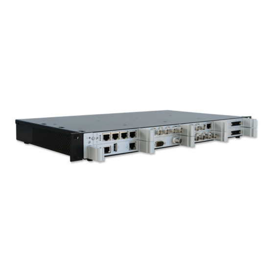
- Page 3 Front view (Frontansicht) IMS-M1000-S...
-
Page 4: Table Of Contents
Table of Contents 1 Imprint 2 Safety instructions for building-in equipment Additional Safety Hints ......... . . Supply Voltage . - Page 5 11.6.21 VSG - Video Sync Generator ........12 Declaration of Conformity Date: 6th September 2017 IMS-M1000-S...
-
Page 6: Imprint
1 Imprint 1 Imprint Meinberg Funkuhren GmbH & Co. KG Lange Wand 9, 31812 Bad Pyrmont / Germany Phone: + 49 (0) 52 81 / 93 09 - 0 Fax: + 49 (0) 52 81 / 93 09 - 30 Internet: http://www.meinberg.de... -
Page 7: Safety Instructions For Building-In Equipment
• Assembling and disassembling of the power connector is only allowed if the device is disconnected from power supply (e.g. trough primary side line protection). • All feed lines are sufficiently protected and dimensioned. Fuse: T2.5A Connector Diameter: - 2,5mm / 17AWG - 13AWG Date: 6th September 2017 IMS-M1000-S... -
Page 8: Additional Safety Hints
To ensure safe operation supply mains connected to this decice must be equipped with a fuse and a fault- current circuit breaker according to the applicable national standards for safe operation. The device must be connected to a protective earth with low grounding resistance according to the applicable national rules. IMS-M1000-S Date: 6th September 2017... -
Page 9: Cabling
Do not carry out any installation or maintenance work on the antenna system or cabling when there is a potential risk of lightning. Surge Voltage Protector Due to extremely high currents associated with lightning no surge protection device can provide absolute safety from the impacts caused by lightning! Date: 6th September 2017 IMS-M1000-S... -
Page 10: Replacing The Lithium Battery
The mounting components (without a cable) are included. 1: Screw M4x6 2: Tooth washer M4 3: Plain washer M4 4: Ring or fork lug 5: Nomel washer Note: Use a grounding cable with >= 1,5mm Please ensure a correct crimp-connection! IMS-M1000-S Date: 6th September 2017... -
Page 11: Lantime S-Chassis: Putting In Operation
LANTIME the login message appears (press RETURN for initial connection): After the connection is successfully established use your login credentials in the welcome screen to enter a console. Welcome to Meinberg LANTIME login: _ Default settings are: Login: root Password: timeserver (It may be the case to press a RETURN button again). -
Page 12: The Modular System Lantime
(e.g. VP100/20/NET). In order to avoid a service interruption several LANTIME NTP servers can be installed in the same network to obtain redundancy. IMS-M1000-S Date: 6th September 2017... -
Page 13: Network Timeserver With Gnss Synchronized Time Base
After the network connection has been established the time server can also be configured and monitored remotely from a workstation via TELNET or FTP. An integrated web server enables access to the LANTIME by using an ordinary web browser. Date: 6th September 2017 IMS-M1000-S... -
Page 14: Mounting The Gps Antenna
[dB]/100m RG58/CU RG213 10.5mm (1)This specifications are made for antenna/converter units produced after January, 2005 The values are typically ones; the exact ones are to find out from the data sheet of the used cable IMS-M1000-S Date: 6th September 2017... -
Page 15: Antenna Assembly With Surge Voltage Protection
GPS Antenna N-Norm female N-Norm male Cable Slot N-Norm male N-Norm female as short as possible N-Norm female Meinberg GPS N-Norm male N-Norm male female Ground lead to PE rail or BNC male female (Protective Earth) Cable ca. 1,5 mm Ø... -
Page 16: Antenna Short-Circuit
In case of an antenna line short-circuit the following message appears in the display: If this message appears the clock has to be disconnected from the mains and the defect eliminated. After that the clock can be powered-up again. The antenna supply voltage must be 15V IMS-M1000-S Date: 6th September 2017... -
Page 17: Booting The Gnss Receiver
This mode is called Cold Boot. It takes 12 minutes until the new almanac is complete and the system switches to Warm Boot mode, scanning for other satellites. Date: 6th September 2017 IMS-M1000-S... -
Page 18: Booting The Single Board Computer
The NTPD tries to keep the offset below +-128 ms; if the offset becomes too large, the system time is set with the receiver’s time. Typically values for the offset are +-5 ms after the NTPD has already synchronized. IMS-M1000-S Date: 6th September 2017... -
Page 19: Configuration User Interface
To set up a HTTP connection the following address is to enter in a web browser: http://198.168.10.10 // LANTIME IP address password: timeserver To set up a Secure HTTP (HTTPS) connection the following address is entered in a web browser: https://198.168.10.10 // LANTIME IP address password: timeserver Date: 6th September 2017 IMS-M1000-S... -
Page 20: The Graphical User Interfaces
Connect to the web interface by entering the following address into the address field of your web browser: http://198.168.10.10 (You need to replace 198.168.10.10 with the IP address of your LANTIME). Default Login User: root Password: timeserver IMS-M1000-S Date: 6th September 2017... - Page 21 Network information - first interface Receiver status NTP status Last messages By using the navigation on top of the page you can reach a number of configuration menus, which are described in the next chapters. Date: 6th September 2017 IMS-M1000-S...
-
Page 22: Attachment: Technical Information
11.2 ACM - Active Cooling Module The Active Cooling Module allows the installation of the M1000 safely within the temperature specification. The ACM is easily field-replaceable and allows for a hot-plug replacement without the need to power down the unit. IMS-M1000-S Date: 6th September 2017... -
Page 23: Available Modules And Connectors
75 Ohm (Bits) shielded data line 10MHz sine shielded data line DFK-3 Error Relay Signal Inputs: BNC, RJ45 E1/T1, var. Freq. shielded data line 10MHz, PPS, IRIG, PP shielded data line Date: 6th September 2017 IMS-M1000-S... -
Page 24: Terminal (Console)
• between different LANTIMEs • Keypad locking for secure • using the keypad of the LCD • Transfer of log files • Install Software Updates • Upload and download secure certificates • (SSL, SSH) and passwords IMS-M1000-S Date: 6th September 2017... -
Page 25: Ims Module Options
The IMS system LANTIME M1000 is available in two different versions. A standard version with a single receiver module and in a redundant design, which allows the use of two Meinberg receivers. In this case the configuration of the I/O slots is characterized by the availability of the slots for input signals. -
Page 26: Power Supply 100-240 V Ac/Dc
5pin DFK Hotplug: It is possible to remove or install the power supply out of the terminal equipment during operation. Pin Assignment: 1: N 2: not connected 3: GND (Ground) 4: not connected 5: L IMS-M1000-S Date: 6th September 2017... -
Page 27: Power Supply 20-72 V Dc
Class 1 - regarding EN 60950 Hotplug: It is possible to remove or install the power supply out of the terminal equipment during operation. Pin Assignment: 1: not connected 2: - 3: GND (Ground) 4: + 5: not connected Date: 6th September 2017 IMS-M1000-S... -
Page 28: Gps Clock
Nav.: green: positioning successfully Ant: red: antenna faulty or not connected yellow: the clock is synchronized by an external Signal - MRS mode (PPS, IRIG ...) Fail: red: time has not synchronized IMS-M1000-S Date: 6th September 2017... - Page 29 Pin 2: CS (Chip Select) Pin 3: MOSI (Master Out, Slave In) Pin 4: MISO (Master In, Slave Out) Pin 5: GND Attention: Use this plug only to connect a MEIN- BERG IMS-XHE Rubidium expansion chassis. Date: 6th September 2017 IMS-M1000-S...
-
Page 30: Gnss Clock
Nav. green: positioning successfully red: antenna faulty or not connected yellow: the clock is synchronized by an external Signal - MRS mode (PPS, IRIG ...) Fail red: time has not synchronized IMS-M1000-S Date: 6th September 2017... - Page 31 Pin 2: CS (Chip Select) Pin 3: MOSI (Master Out, Slave In) Pin 4: MISO (Master In, Slave Out) Pin 5: GND Attention: Use this plug only to connect a MEIN- BERG IMS-XHE Rubidium expansion chassis. Date: 6th September 2017 IMS-M1000-S...
-
Page 32: Pzf Clock
field strength needed for the correlation receiption is detected Ant Fail: red: antenna faulty or not connected Fail: red: time is not synchronized Pin Assignment of the DSUB9 Connectors (male): Pin 2: RxD Pin 3: TxD Pin 5: GND IMS-M1000-S Date: 6th September 2017... -
Page 33: Tcr Clock - Time Code Reader And Generator
(flashing): Jitter too large Fail red: the internal timing of the TCR180 is in holdover mode off: the internal timing of the TCR180 is synchronized to the received time code (Lock) Date: 6th September 2017 IMS-M1000-S... - Page 34 IRIG-B123 / B122 / / B126 / B127 / B002 / B003 / B006 / B007 IRIG-G142 / G146 / G002 / G006 AFNOR NFS 87-500 C37.118 IEEE1344 Accuracy of Time Base Required Accuracy of Time Code Source: max 100 sec Jitter / offset 1E-5 IMS-M1000-S Date: 6th September 2017...
- Page 35 7E2, 8N1, 8N2, 8E1, 7N2, 7E1, 801 Mode of operation: string per second string per minute string on request Time telegram: Meinberg Standard, Uni Erlangen, SAT, Meinberg Capture, ION, Computime, SPA, RACAL Capture Inputs Triggered by falling TTL slope Pulse repetition time: 1.5 msec min.
- Page 36 VG Connector - 5 V 450 mA Dimension: Euro card, 100mm x 160mm, 1.5mm Epoxy Ambient Temperature: 0 ... 50 C Humidity: max. 85 % Pin Assignment of the DSUB9 Connectors (male): Pin 2: RxD Pin 3: TxD Pin 5: GND IMS-M1000-S Date: 6th September 2017...
-
Page 37: Rsc Switch Card
Deactivation of outputs is possible by a display in the “RSC Cntl” menu. Display Menu: Switch Unit -> RSC Cntl -> REMOTE : enable Date: 6th September 2017 IMS-M1000-S... - Page 38 1/2: selected reference clock Menu "Switch Unit -> RSC Cntl" REMOTE: enable/disable Switching between automatic and remote operation OUTPUTS: enabled/disabled Disabling outputs during a free run Selected Clk: Selection of the currently active reference clock IMS-M1000-S Date: 6th September 2017...
-
Page 39: Lan-Cpu
R T N A Cache Memory: 16 KB 2nd Level Cache Flash Disk: 1 GB CONSOLE Network 38400 / 8N1 Connector: 10/100 Base-T with RJ45-Jack State LEDs: Connect, Activity and Speed of the network connection Date: 6th September 2017 IMS-M1000-S... -
Page 40: Mri - Standard Reference Input Signals
LED B: green, if 10 MHz or PPS or both signals are available at the same time Figure right: MRI - standard input signals via BNC female connectors Power Requirements: 5 V +-5%, 50 mA IMS-M1000-S Date: 6th September 2017... - Page 41 Input signal: 600mV to 8 V (Mark, peak-to-peak) 1 x Time Code unmodulated input BNC connector, isolated by opto-coupler Insulation voltage: 3750 Vrms Internal series resistor: 330 Ohm, Max. input current: 25 mA Diode forward voltage: 1.0 V...1.3 V Date: 6th September 2017 IMS-M1000-S...
-
Page 42: Esi - Telecom Synchronisation References
LED B green, if Clock and Framed available flashing green, if only Clock available flashing yellow, if only Framed available off, if no signal Pin assignment of the RJ-45 jacks (input 3 + 4) IMS-M1000-S Date: 6th September 2017... - Page 43 An ESI card is, as the MRI card, dedicated to one specific clock module (depending on the slot it is installed in) and can be installed in both ESI as well as MRI slots. Configurable Inputs Input 1: The input 1 is dedicated to 1PPS pulse synchronization. Date: 6th September 2017 IMS-M1000-S...
- Page 44 A discontinuity of an integer number of cycles in the measured carrier phase resulting from a temporary loss of input signal. The maximum slip number can be selected in range between 0.5 – 3 cycles, with 1.5 as a default value. Input 3: see Input 2. IMS-M1000-S Date: 6th September 2017...
- Page 45 TNC will be allowed for synchronization, whereas signal coming from Synchronous Equipment Timing Source (SETS) will not be accepted. Sa Bits With Sa Bits you can select one of the Sa4 to Sa8 bits which is allocated for SSM quality messages. Date: 6th September 2017 IMS-M1000-S...
-
Page 46: Lne-Gbe: Network Expansion With Gigabit Support And Sfp Option
1000BASE-T SFP Cable: Multimode Fiber GI 50/125 m or GI 62,5/125 m gradient fiber Singlemode Fiber E9/125 m monomode fiber Link Speed Electrical: 1000 Base-T Fiber optical: 1000-FX Figure right: LNE-GbE and LNE-GbE with SFP Option IMS-M1000-S Date: 6th September 2017... - Page 47 I/O slot order by which the modules are inserted. In a factory assembling, LNE modules are sorted in an ascending order starting from left to right (see the corresponding figure above). LAN 0 is therefore always the first network interface of the LAN-CPU. Date: 6th September 2017 IMS-M1000-S...
- Page 48 IPv6 Mode: This mode must be activated here. MAC-Address: Displays the unique MAC address of the physical interface. Assigned Virtual Interfaces: In the Ethernet Interfaces menu (see below) virtual network interfaces can be added. IMS-M1000-S Date: 6th September 2017...
- Page 49 With VLAN, this function can be enabled and configured. Cluster: The cluster function can be activated with this submenu and additional Parameters such as multicast or unicast mode, TCP / IP address and subnet mask can be set up here. Date: 6th September 2017 IMS-M1000-S...
- Page 50 ; saveconfig network After the nicmgr has finished it’s procedure, have a look again at the web UI of the LANTIME. You should now be able to see the interfaces of the LNE module. IMS-M1000-S Date: 6th September 2017...
- Page 51 Now log in to the LANTIME Command-Line-Interface using SSH, Telnet or a serial connection. Once you are logged in, exexute the following command. nicmgr autoremove ; saveconfig network This will delete the interface out of the LANTIME configuration files. After that the webinterface should display the "old" state again. Date: 6th September 2017 IMS-M1000-S...
-
Page 52: Hps-100: Ptp / Synce / Hardware Ntp Interface
USB 1.1 / USB 2.0 full-speed, Micro USB female connector Signal Outputs: 2x SMA (50 Ohm) connectors configurable signals: 1PPS, 10MHz, 2048kHz CPU: 825 MHz Cortex A9 Dual Core on SOC Time Stamp Accuracy: 8 ns IMS-M1000-S Date: 6th September 2017... - Page 53 - yellow uncalibrated red - red stopped Client Licenses: License Unicast Delay PTPv1 Clients Req./s Req./s Monitoring ————————————————————————————————————————————- PL-A 1024 1600 PL-B 32768 51200 PL-C 65536 102400 PL-D 1024 131072 204800 PL-E 2048 262144 409600 Date: 6th September 2017 IMS-M1000-S...
- Page 54 11 Attachment: Technical Information A detailed configuration guide you will find in the corresponding firmware manual of the system. See chapter "The Web Interface -> Configuration: PTP V2". IMS-M1000-S Date: 6th September 2017...
-
Page 55: Tsu V3: Ieee-1588 Time Stamp Unit
LED A - LED B: Shows the current State of the TSU yellow - yellow Listening green - off Master Mode off - green Slave Mode yellow - off Passiv Mode off - yellow uncalibrated red - red stopped Date: 6th September 2017 IMS-M1000-S... -
Page 56: Cpe And Bpe Output Modules (Frontend - Backend, Eurocard)
BPE) or for autonomously generating a wide range of different signals by using a microprocessor (on a CPE). The front-end makes a selection of the signals available on physical connectors. CPE - Backend BPE - Backend IMS-M1000-S Date: 6th September 2017... - Page 57 3 and output 4 Figure right: BPE Outputs BPE-2000 Standard outputs - BNC female: PPS, 10MHz, TC DCLS and TC AM BPE 5000 Fiber Optic ST-Connectors PPS, 10MHz, TC DCLS und TC AM Date: 6th September 2017 IMS-M1000-S...
- Page 58 4 x BNC female Out 1 - Out 4: TC DCLS BPE-2050 4 x BNC female Out 1 - Out 3: TC DCLS Out 4: TC AM BPE-2080 4 x BNC female Out 1 - Out 4: 2.048kHz IMS-M1000-S Date: 6th September 2017...
- Page 59 Figure: CPE Frontends CPE-1000: 4 config. outputs via BNC female CPE-5000: 4 config. outputs / FO - ST connectors CPE-2500: 4 x prog. Pulses (DFK-2) / 1 x TC AM (BNC) Date: 6th September 2017 IMS-M1000-S...
- Page 60 The CPE 3000 module has two serial ports (COM A and B) for various output signals. The two interfaces can also be used for communication with other devices. The possible pin assignments and module types are listed below: IMS-M1000-S Date: 6th September 2017...
- Page 61 Generated IRIG output codes (B002+B122 ...) Prog. Out Programmable output Serial-1 Setting the serial port parameters (baud rate, framing, time telegram and operating mode) Figure: Menu Tab "Synthesizer" Frequency for selecting the Frequency Synthesizer option in the menu "Prog. Out" Date: 6th September 2017 IMS-M1000-S...
- Page 62 Figure: Menu Tab "IRIG Out" Selection of the IRIG code (IRIG DCLS only) Figure: Menu Tab "Prog. Out" Selection of the signal option for the programmable pulse output (PPO) Figure: Menu Tab "Serial 1/2" Setting of the parameters for the serial port IMS-M1000-S Date: 6th September 2017...
- Page 63 Current Consumption: 5 V +-5%, 100 mV CPE-1002 Configuration via Web Interface The settings of the Time Capture module can be done in the IO-Config menu. Common The corresponding time zone can be selected here. Date: 6th September 2017 IMS-M1000-S...
- Page 64 The "on request ‘¿ only" mode allows you to query the Capture Events on request or store them in a log file of the LANTIME. Capture Event_1/2 This text box displays the contents of the log file. In addition, the current capture event memory can also be deleted here. IMS-M1000-S Date: 6th September 2017...
-
Page 65: Liu - Line Interface Unit
Power T1 E1 Power: Init blue during initialisation, green in normal operation mode green selected mode T1 red: output disabled yellow: signal quality unknown green selected mode E1 red: output disabled yellow: signal quality unknown Date: 6th September 2017 IMS-M1000-S... - Page 66 IMS-LIU Telecom Output Signals The board LIU (Line Interface Unit) was designed to convert the GPS-locked standard frequency of a precon- nected Meinberg satellite controlled clock (GPS and GLONASS) into several timing signals that can be used for various synchronization or measurement tasks.
- Page 67 G703-13, balanced isolation 1544 kHz or 2048 kHz isolation micro controller amplifier amplifier clock outputs G703-13, unbalanced amplifier 1544 kHz or 2048 kHz framer & low pass filter 4.096 MHz line interface amplifier Date: 6th September 2017 IMS-M1000-S...
- Page 68 BNC connectors or balanced via RJ45 connectors. Two different line codes used for error correction are known for the transmission of framed signals. The board LIU generates B8ZS- (in T1-mode) or HDB3-coded (in E1-mode) output signals by standard. IMS-M1000-S Date: 6th September 2017...
- Page 69 Pulse templates The following pulse templates are required by ANSI (T1-mode) and CCITT (E1-mode) for output signals in telecom applications. The board LIU meets these recommendations. T1 (T.403): E1 (G.703): Date: 6th September 2017 IMS-M1000-S...
- Page 70 Power T1 E1 LIU-A4000 LIU-A0040 LIU-A0004 LIU-A2020 LIU-A2002 LIU_A0202 LIU_A0400 LIU-A1111 BITS (4/0) Clock (4/0) Clock (0/4) BITS (2/0) BITS (2/0) BITS (0/2) BITS (0/4) BITS (1/1) Clock (2/0) Clock (0/2) Clock (0/2) Clock (1/1) IMS-M1000-S Date: 6th September 2017...
-
Page 71: Lno - 10Mhz Sinus Output Module
OCXO in warm up phase 10MHz reference not available Quality of the reference signal is not sufficient All LEDs green: Normal operation, outputs activated Associated LED red: defect output or short circuit during normal operation Date: 6th September 2017 IMS-M1000-S... -
Page 72: Fdm - Frequency Deviation Monitoring
/ not sync. yellow signal not available green blinking Timesync green Accurate LED A: green FD (Frequency Deviation) within the configured limits FD Overflow LED B: green TD (Time Deviation) within the configured limits TD Overflow IMS-M1000-S Date: 6th September 2017... - Page 73 96-pin VG-rail DIN 41612, X1, Power Line In Power supply: +5V DC Current consumption: 0.4 A - 1 A (depending on oscillator type) Ambient temperature: 0 ... 50 C / 32 ... 122 F Humidity: Max. 85% Date: 6th September 2017 IMS-M1000-S...
- Page 74 In redundant mode, the jumpers on the REL1000 are set as follows: Please note: The REL1000 can only be used for the IMS system M500 in the following jumper setting: IMS-M500: Relais A: Clock 1 Relais B: Relais C: 10MHz IMS-M1000-S Date: 6th September 2017...
- Page 75 Technical Specification ERROR Relays: Switching Voltage: 220 V DC / 250 V AC Switching Load: 60 W /62.5 VA UL/CSA: 0.3 A 125 V AC 0.3 A 110 V DC 30 V DC Response Time: ca.3 ms Date: 6th September 2017 IMS-M1000-S...
- Page 76 4 x BNC (2.5V TTL into 75 Ohm) outputs with configureable frequencies Input Signal: 10MHz, sinewave or square pulse Current Consumption: 5 V +- 5%, @400 mA Ambient Temperature: 0 ... 50 C / 32 ... 122 F Humidity: 85% max. IMS-M1000-S Date: 6th September 2017...
- Page 77 Frequency Out 3 = 44,1 kHz * 1/4 ————————————————- Frequency Out 3 = 11,025 kHz Overview Configuration SCG Sound Clock Generator Outputs 1-4 Output Type: Studio Clock Out State: Disabled Enabled Base Frequency: 32kHz 44.1kHz 48kHz Scale: 1/8 to 256 Date: 6th September 2017 IMS-M1000-S...
- Page 78 Power Consumption: 5 V +- 5%, 250 mA BNC Connectors: 2x BNC female, unbalanced, 300 mV @ 75 2x BNC female, unbalanced, 2.5 V TTL @ 75 Ambient Temperature: 0 ... 55 C Humidity: Max. 85% IMS-M1000-S Date: 6th September 2017...
- Page 79 Video Out Epoch: Format: 720p 50Hz 1080i 25Hz 720p 59.94Hz 1080i 59.94Hz Phase Offset: [Offset Value] —————————————————- Output 2: —————————————————- Output Type: Video Out Epoch: like Output 1 Format: NTSC Phase Offset: [Offset Value] —————————————————- Date: 6th September 2017 IMS-M1000-S...
- Page 80 SD H-Sync SD V-Sync SD Frame HD H-Sync HD V-Sync HD Frame HD Blank —————————————————- With the menu tab "Misc", the configuration of the VSG can be stored directly in the EEPROM of the card. IMS-M1000-S Date: 6th September 2017...
-
Page 81: Declaration Of Conformity
12 Declaration of Conformity Konformitätserklärung Doc ID: LANTIME M1000-S-2017-09-06 Hersteller Meinberg Funkuhren GmbH & Co. KG Manufacturer Lange Wand 9, D-31812 Bad Pyrmont erklärt in alleiniger Verantwortung, dass das Produkt, declares under its sole responsibility, that the product Produktbezeichnung LANTIME M1000-S Product Designation auf das sich diese Erklärung bezieht, mit den folgenden Normen übereinstimmt...
Need help?
Do you have a question about the IMS-M1000-S and is the answer not in the manual?
Questions and answers