
Subscribe to Our Youtube Channel
Related Manuals for Meinberg IMS-M3000


Summary of Contents for Meinberg IMS-M3000
- Page 1 MANUAL IMS-M3000 Modular Sync. System and NTP Server 21st August 2019 Meinberg Funkuhren GmbH & Co. KG...
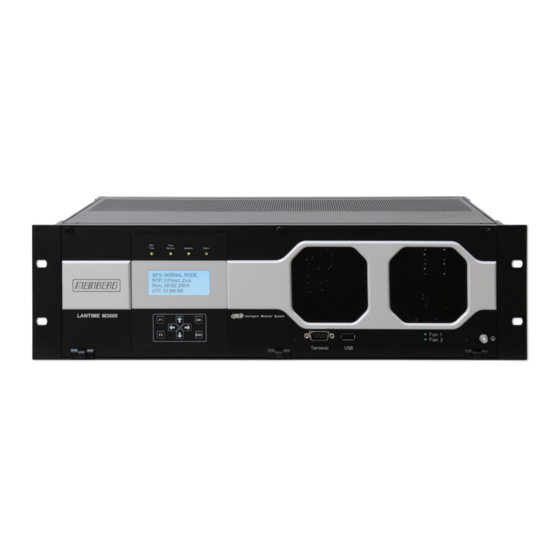
- Page 3 Front view (Frontansicht) IMS-M3000...
- Page 4 Rear view (Rückansicht) IMS-M3000...
-
Page 5: Table Of Contents
Table of Contents 1 Imprint 2 Safety instructions for building-in equipment Additional Safety Hints ......... . . Supply Voltage . - Page 6 ........102 13 Declaration of Conformity Date: 21st August 2019 IMS-M3000...
-
Page 7: Imprint
1 Imprint 1 Imprint Meinberg Funkuhren GmbH & Co. KG Lange Wand 9, 31812 Bad Pyrmont / Germany Phone: + 49 (0) 52 81 / 93 09 - 0 Fax: + 49 (0) 52 81 / 93 09 - 230 Internet: https://www.meinbergglobal.com... -
Page 8: Safety Instructions For Building-In Equipment
• Assembling and disassembling of the power connector is only allowed if the device is disconnected from power supply (e.g. trough primary side line protection). • All feed lines are sufficiently protected and dimensioned. Fuse: T2.5A Connector Diameter: - 2,5mm / 17AWG - 13AWG Date: 21st August 2019 IMS-M3000... -
Page 9: Additional Safety Hints
To ensure safe operation supply mains connected to this decice must be equipped with a fuse and a fault- current circuit breaker according to the applicable national standards for safe operation. The device must be connected to a protective earth with low grounding resistance according to the applicable national rules. IMS-M3000 Date: 21st August 2019... -
Page 10: Cabling
Do not carry out any installation or maintenance work on the antenna system or cabling when there is a potential risk of lightning. Surge Voltage Protector Due to extremely high currents associated with lightning no surge protection device can provide absolute safety from the impacts caused by lightning! Date: 21st August 2019 IMS-M3000... -
Page 11: Replacing The Lithium Battery
Tooth washer Nut M4 Nomel washer Nomel washer Flat connector Tooth washer Note: Use a grounding cable with >= 1,5mm Please ensure a correct crimp connection! Observe torque when mounting the grounding cable! IMS-M3000 Date: 21st August 2019... -
Page 12: Quick Start
NOTE: These settings are related to the first Ethernet connection (ETH0). After this all further settings can be done via network interface, either by using a WEB browser or a Telnet Session. Default user: root Default password: timeserver Date: 21st August 2019 IMS-M3000... -
Page 13: The Modular System Lantime
VP100/20/NET that is accessed via network connection. In order to avoid a service interruption several LANTIME NTP servers can be installed in the same network to obtain redundancy. IMS-M3000 Date: 21st August 2019... -
Page 14: Mounting The Gps Antenna
- Do not carry out any work on the antenna system or the antenna cable if there is a risk of a lightning strike. - Do not carry out any work on the antenna system if the safety distance to free lines and sequential circuits is exceeded. Date: 21st August 2019 IMS-M3000... -
Page 15: Antenna Cable
If this message appears the clock has to be disconnected from the mains and the defect eliminated. After that the clock can be powered-up again. The supply voltage for the antenna/converter unit is approx. 18.5 V DC in idle mode and approx. 16 V DC when the GPS antenna is connected. IMS-M3000 Date: 21st August 2019... -
Page 16: Antenna Assembly With Surge Voltage Protection
GPS Antenna N-Norm female N-Norm male Cable Slot N-Norm male N-Norm female as short as possible N-Norm female Meinberg GPS N-Norm male N-Norm male female Ground lead to PE rail or BNC male female (Protective Earth) Cable ca. 1,5 mm Ø... -
Page 17: 40Db Multi Gnss L1 Timing Antenna With Integrated Lightning Protection
The antenna cable length can be up to 70 meters if a H155 low-loss coaxial cable is used. Mounting and Installation of the GNSS/L1 Antenna IMS-M3000 Date: 21st August 2019... - Page 18 Multi GNSS Antenna free view to the sky! Type-N female Type-N male as short as possible MEINBERG GNSS Type SMA male female Connection to earth rail (Protective Earth) cable diameter ca. 1,5 mm Ø Figure: Schematic diagram of mounting the Multi GNSS Antenna...
-
Page 19: Gnss Antenna For Mobile Applications
- Do not carry out any work on the antenna system or the antenna cable if there is a risk of a lightning strike. - Do not carry out any work on the antenna system if the safety distance to free lines and sequential circuits is exceeded. IMS-M3000 Date: 21st August 2019... -
Page 20: Booting The Single Board Computer
The NTPD tries to keep the offset below +-128 ms; if the offset becomes too large, the system time is set with the receiver’s time. Typically values for the offset are +-5 ms after the NTPD has already synchronized. Date: 21st August 2019 IMS-M3000... -
Page 21: Configuration User Interface
To set up a HTTP connection the following address is to enter in a web browser: http://198.168.10.10 // LANTIME IP address password: timeserver To set up a Secure HTTP (HTTPS) connection the following address is entered in a web browser: https://198.168.10.10 // LANTIME IP address password: timeserver IMS-M3000 Date: 21st August 2019... -
Page 22: The Menues In Detail
Parameter / Check Network Linkup“) is not connected „Alarm“ off: no error at moment red: general error – more information will be shown on display. When pressing „F1“ from main menu a short description for menu navigation will be displayed: Date: 21st August 2019 IMS-M3000... - Page 23 Local Strat. Network Restart NTP System PTP IEEE1588 Ref. Time -> Interfaces <- Time Service Global Cfg. ->Network <- Services System Ref. Time > Time Zone < Time Service Restart Network Factory Reset ->System <- IMS-M3000 Date: 21st August 2019...
-
Page 24: The Graphical User Interfaces
Connect to the web interface by entering the following address into the address field of your web browser: http://198.168.10.10 (You need to replace 198.168.10.10 with the IP address of your LANTIME). Default Login User: root Password: timeserver Date: 21st August 2019 IMS-M3000... -
Page 25: The Web Interface
Network information - first interface Receiver status NTP status Last messages By using the navigation on top of the page you can reach a number of configuration menus, which are described in the next chapters. IMS-M3000 Date: 21st August 2019... -
Page 26: Attachment: Technical Information
(see chapter Retrofit the System with an Active Cooling Module) Protection Rating: IP20 Physical Dimensions: 442 (484) mm wide x 132,25 mm high x 270 (304) mm deep Ambient Temperature: 0 ... 50 C Storage Temperature -20 ... 70 Humidity: 85 % max. Date: 21st August 2019 IMS-M3000... - Page 27 (1U at the bottom and the top). In the right figure the air flow during device in operation with ACM and no space between devices in a server rack is depicted. IMS-M3000 Date: 21st August 2019...
-
Page 28: Acm - Active Cooling Module
Fig. 4: Lock the plug into the system Fig. 2: Compact ACM Module with two fans Fig. 5: The switch interrupts the power circuit after opening the front Date: 21st August 2019 IMS-M3000... -
Page 29: Available Modules And Connectors
DFK-3 Error Relay Signal Inputs: BNC, RJ45 E1/T1, var. Freq. shielded data line BNC / FST 10MHz, PPS, IRIG, PP shielded data line Input / Output Modules: PPS, 10MHz shielded data line IMS-M3000 Date: 21st August 2019... -
Page 30: Terminal (Console)
• between different LANTIMEs • Keypad locking for secure • using the keypad of the LCD • Transfer of log files • Install Software Updates • Upload and download secure certificates • (SSL, SSH) and passwords Date: 21st August 2019 IMS-M3000... -
Page 31: Replacement Or Installation Of A Hot-Pluggable Ims Module
Non-observance can cause damage to the module and the chassis. Make sure that the module is securely locked into the connector block before you fasten the two screws. Now you can put the installed module into operation. Attachment points of an 1U IMS system IMS-M3000 Date: 21st August 2019... -
Page 32: Important Hints For Hot-Pluggable Ims Modules
The central management unit is not "hot swappable", i.e. the system must be disconnected from mains before replacement. RSC/SPT The RSC switching card is not "hot swappable", i.e. the system must be disconnected from the mains before replacement. Date: 21st August 2019 IMS-M3000... -
Page 33: Ims Module Options
- Never work with open terminals and plugs while the power is on. - All connectors must be protected against touching live parts with a suitable plug housing! - Note: Always ensure safe wiring! - Important: The device must be connected to a proper grounding (PE). IMS-M3000 Date: 21st August 2019... -
Page 34: Power Supply 20-60 V Dc
= 2.5 A Nominal voltage range: = 24 V Maximum voltage range: = 10-36 V Nominal current: = 2.5 A Output Parameter ——————————————————————————– Maximum power: = 50 W Maximum thermal energy: = 180.00 kJ/h (170.61 BTU/h) therm Date: 21st August 2019 IMS-M3000... -
Page 35: Gps Clock
Nav.: green: positioning successfully Ant: red: antenna faulty or not connected yellow: the clock is synchronized by an external Signal - MRS mode (PPS, IRIG ...) Fail: red: time has not synchronized IMS-M3000 Date: 21st August 2019... - Page 36 Pin 2: String * * The following timestrings (time telegrams) can be used: NMEA RMC NMEA GGA NMEA ZDA Meinberg Standard Uni Erlangen Pin Assignment of the optional XHE-SPI Connectors: A1: PPS In A2: PPS Out Pin 1: SCL_Out (SPI Clock)
-
Page 37: Gnss Clock
Nav. green: positioning successfully red: antenna faulty or not connected yellow: the clock is synchronized by an external Signal - MRS mode (PPS, IRIG ...) Fail red: time has not synchronized IMS-M3000 Date: 21st August 2019... - Page 38 Pin 2: String * * The following timestrings (time telegrams) can be used: NMEA RMC NMEA GGA NMEA ZDA Meinberg Standard Uni Erlangen Pin Assignment of the optional XHE-SPI Connectors: A1: PPS In A2: PPS Out Pin 1: SCL_Out (SPI Clock)
-
Page 39: Gns-Uc Clock
12 Attachment: Technical Information 12.7.6 GNS-UC Clock GNSS receiver with UpConverter for operation on a standard Meinberg GPS antenna/converter unit. Type of receiver: GPS / Galileo receiver Number of channels: 72 GPS: L1C/A Galileo: E1B/C 181-UC 181-UC Accuracy of Pulses: Dependant on oscillator option <... - Page 40 Pin 2: String * * The following timestrings (time telegrams) can be used: NMEA RMC NMEA GGA NMEA ZDA Meinberg Standard Uni Erlangen Pin Assignment of the optional XHE-SPI Connectors: A1: PPS In A2: PPS Out Pin 1: SCL_Out (SPI Clock)
-
Page 41: Pzf Clock
Fail: red: time is not synchronized Pin Assignment of the DSUB9 Connectors (male): Pin 2: RxD Pin 3: TxD Pin 5: GND Synchronization with PPS + String: Pin 1: PPS Pin 2: RxD IMS-M3000 Date: 21st August 2019... -
Page 42: Tcr Clock - Time Code Reader And Generator
(flashing): Jitter too large Fail red: the internal timing of the TCR180 is in holdover mode off: the internal timing of the TCR180 is synchronized to the received time code (Lock) Date: 21st August 2019 IMS-M3000... - Page 43 IRIG-B123 / B122 / / B126 / B127 / B002 / B003 / B006 / B007 IRIG-G142 / G146 / G002 / G006 AFNOR NFS 87-500 C37.118 IEEE1344 Accuracy of Time Base Required Accuracy of Time Code Source: max 100 sec Jitter / offset 1E-5 IMS-M3000 Date: 21st August 2019...
- Page 44 7E2, 8N1, 8N2, 8E1, 7N2, 7E1, 801 Mode of operation: string per second string per minute string on request Time telegram: Meinberg Standard, Uni Erlangen, SAT, Meinberg Capture, ION, Computime, SPA, RACAL Capture Inputs Triggered by falling TTL slope Pulse repetition time: 1.5 msec min.
- Page 45 0 ... 50 C Humidity: max. 85 % Pin Assignment of the DSUB9 Connectors (male): Pin 2: RxD Pin 3: TxD Pin 5: GND Synchronization with PPS + String: Pin 1: PPS Pin 2: RxD IMS-M3000 Date: 21st August 2019...
-
Page 46: Rsc Switch Card
In this operation mode the selection of the reference clock is done by a display menu. A switchover of the reference clock in case of an error does not happen, pulse and frequency outputs and the serial interfaces are always enabled. Deactivation of outputs is possible by a display in the “RSC Cntl” menu. Date: 21st August 2019 IMS-M3000... - Page 47 1/2: selected reference clock Menu "Switch Unit -> RSC Cntl" REMOTE: enable/disable Switching between automatic and remote operation OUTPUTS: enabled/disabled Disabling outputs during a free run Selected Clk: Selection of the currently active reference clock IMS-M3000 Date: 21st August 2019...
- Page 48 Switch No. 4. Positions: OFF: The RSC board is used in an IMS system. LAN Interface is activated. Switch No. 5-7 Reserves. Switch No. 8. Positions: OFF: The Priority master mode is disabled. Priority master mode is enabled. Date: 21st August 2019 IMS-M3000...
- Page 49 The Priority master is clock 2. IF Switch No. 1 is ON: Switch No. 10. Positions: OFF: Even async, one clock is always enabled. A clock is enabled after the first sync event since a reset. IMS-M3000 Date: 21st August 2019...
-
Page 50: Spt - Single Path Through
Clock: red: as long as the receiver is not synchronized, yet. green: when the receiver is synchronized. Status: blue: during the initialization phase. green: after initialization of the receiver. Current Consumption: 40 mA Date: 21st August 2019 IMS-M3000... -
Page 51: Lan-Cpu
Interfaces - IMS LAN-CPU Serial Interface: RJ45 connector console: 38400 / 8N1, connection via CAB-CONSOLE cable USB Port: install firmware upgrades backup and restore configuration files copy security keys lock / unlock front keys Operating System: GNU/Linux 4.x IMS-M3000 Date: 21st August 2019... - Page 52 FTP, NTPv3 / NTPv4, SNTP, RADIUS, TACACS, FTP, SSH (incl. SFTP, SCP) - SSH v1.3 / SSH v1.5 / SSH v2 (OpenSSH), SNMPv1 (RFC 1157) / SNMPv2c (RFC 1901-1908) / SNMP v3 (RFC 3411-3418), Telnet (RFC 854-RFC 861) Date: 21st August 2019 IMS-M3000...
-
Page 53: Mri - Standard Reference Input Signals
LED B: green, if 10 MHz or PPS or both signals are available at the same time Figure right: MRI - standard input signals via BNC female connectors Power Requirements: 5 V +-5%, 50 mA IMS-M3000 Date: 21st August 2019... - Page 54 Input signal: 600mV to 8 V (Mark, peak-to-peak) 1 x Time Code unmodulated input BNC connector, isolated by opto-coupler Insulation voltage: 3750 Vrms Internal series resistor: 330 Ohm, Max. input current: 25 mA Diode forward voltage: 1.0 V...1.3 V Date: 21st August 2019 IMS-M3000...
-
Page 55: Esi - Telecom Synchronisation References
LED B green, if Clock and Framed available flashing green, if only Clock available flashing yellow, if only Framed available off, if no signal Pin assignment of the RJ-45 jacks (input 3 + 4) IMS-M3000 Date: 21st August 2019... - Page 56 An ESI card is, as the MRI card, dedicated to one specific clock module (depending on the slot it is installed in) and can be installed in both ESI as well as MRI slots. Configurable Inputs Input 1: The input 1 is dedicated to 1PPS pulse synchronization. Date: 21st August 2019 IMS-M3000...
- Page 57 A discontinuity of an integer number of cycles in the measured carrier phase resulting from a temporary loss of input signal. The maximum slip number can be selected in range between 0.5 – 3 cycles, with 1.5 as a default value. Input 3: see Input 2. IMS-M3000 Date: 21st August 2019...
- Page 58 TNC will be allowed for synchronization, whereas signal coming from Synchronous Equipment Timing Source (SETS) will not be accepted. Sa Bits With Sa Bits you can select one of the Sa4 to Sa8 bits which is allocated for SSM quality messages. Date: 21st August 2019 IMS-M3000...
-
Page 59: Lne-Gbe: Network Expansion With Gigabit Support And Sfp Option
LED St: Init lights blue during initialisation LED In - LED B: Shows the state of the four LAN ports after initialisation green normal operation defective LAN port Figure right: LNE-GbE and LNE-GbE with SFP Option IMS-M3000 Date: 21st August 2019... - Page 60 Distance ———————————————————————————————————————– MULTI MODE: AVAGO AFBR-5710PZ 550 m FINISAR FTLF8524P3BNL 500 m SINGLE MODE: AVAGO AFCT-5710PZ 10 km FINISAR FTLF1318P3BTL 10 km SMARTOPTICS SO-SFP-L120D-C63 80 km RJ-45: AVAGO ABCU-5740RZ 100 m FINISAR FCLF8521P2BTL 100 m Date: 21st August 2019 IMS-M3000...
- Page 61 I/O slot order by which the modules are inserted. In a factory assembling, LNE modules are sorted in an ascending order starting from left to right (see the corresponding figure above). LAN 0 is therefore always the first network interface of the LAN-CPU. IMS-M3000 Date: 21st August 2019...
- Page 62 IPv6 Mode: This mode must be activated here. MAC-Address: Displays the unique MAC address of the physical interface. Assigned Virtual Interfaces: In the Ethernet Interfaces menu (see below) virtual network interfaces can be added. Date: 21st August 2019 IMS-M3000...
- Page 63 With VLAN, this function can be enabled and configured. Cluster: The cluster function can be activated with this submenu and additional Parameters such as multicast or unicast mode, TCP / IP address and subnet mask can be set up here. IMS-M3000 Date: 21st August 2019...
- Page 64 ; saveconfig network After the nicmgr has finished it’s procedure, have a look again at the web UI of the LANTIME. You should now be able to see the interfaces of the LNE module. Date: 21st August 2019 IMS-M3000...
- Page 65 Now log in to the LANTIME Command-Line-Interface using SSH, Telnet or a serial connection. Once you are logged in, exexute the following command. nicmgr autoremove ; saveconfig network This will delete the interface out of the LANTIME configuration files. After that the webinterface should display the "old" state again. IMS-M3000 Date: 21st August 2019...
-
Page 66: Hps-100: Ptp / Synce / Hardware Ntp Interface
USB 1.1 / USB 2.0 full-speed, Micro USB female connector Signal Outputs: 2x SMA (50 Ohm) connectors configurable signals: 1PPS, 10MHz, 2048kHz CPU: 825 MHz Cortex A9 Dual Core on SOC Time Stamp Accuracy: 8 ns Date: 21st August 2019 IMS-M3000... - Page 67 - yellow uncalibrated red - red stopped Client Licenses: License Unicast Delay PTPv1 Clients Req./s Req./s Monitoring ————————————————————————————————————————————- PL-A 1024 1600 PL-B 32768 51200 PL-C 65536 102400 PL-D 1024 131072 204800 PL-E 2048 262144 409600 IMS-M3000 Date: 21st August 2019...
- Page 68 A detailed configuration guide you will find in the corresponding firmware manual of the system. See chapter "The Web Interface -> Configuration: PTP V2". Figure: Webinterface - PTP Menu Global Configuration Date: 21st August 2019 IMS-M3000...
-
Page 69: Tsu V3: Ieee-1588 Time Stamp Unit
Ethernet Interface: Combo Port: 1 x 100/1000BASE-T RJ45 1 x GBIT SFP - Slot Signal Outputs: 2x BNC (50 Ohm) connectors configurable signals: 1PPS, 10MHz, 2048kHz CPU: 1 GHz Dual Core ARM Time Stamp Accuracy:10 ns IMS-M3000 Date: 21st August 2019... - Page 70 LED A - LED B: Shows the current State of the TSU yellow - yellow Listening green - off Master Mode off - green Slave Mode yellow - off Passiv Mode off - yellow uncalibrated red - red stopped Date: 21st August 2019 IMS-M3000...
-
Page 71: Ims Pio: Pps Oder 10Mhz I/O Module
0,5 sec. red -> 0,5 sec. yellow -> 0,5 sec. green -> 0,5 sec. off Normal Operation: LED St. + LED In: green LED P: green, if card is preset to PPS LED C: green, if card is preset to 10MHz IMS-M3000 Date: 21st August 2019... - Page 72 PPS or the 10 MHz reference frequency is output signal at this port. If a port is set to "Input" the incoming signal is compared to the system PPS or to the 10MHz reference frequency. The offset values are displayed in the status window. Date: 21st August 2019 IMS-M3000...
-
Page 73: Cpe And Bpe Output Modules (Frontend - Backend, Eurocard)
BPE) or for autonomously generating a wide range of different signals by using a microprocessor (on a CPE). The front-end makes a selection of the signals available on physical connectors. CPE - Backend BPE - Backend IMS-M3000 Date: 21st August 2019... - Page 74 LED B: green, if the desired signal is present on output 3 and output 4 Figure right: BPE Outputs BPE-2000 Standard outputs - BNC female: PPS, 10MHz, TC DCLS and TC AM BPE 5000 Fiber Optic ST-Connectors PPS, 10MHz, TC DCLS und 2048kHz Date: 21st August 2019 IMS-M3000...
- Page 75 "Clock Programmable Pulse Prog. Out 1". Here the option "PTTI 1PPS" must be selected to get a pulse length of 20 s. IMS-M3000 Date: 21st August 2019...
- Page 76 (4) The outputs COM A and COM B are configured via the upstream receiver in the web interface (Menu "Clock Programable Pulses Prog. Out 1"). The programable pulses PP_0 of the clock are connected to both outputs of the BPE-3050 via the backplane. Date: 21st August 2019 IMS-M3000...
- Page 77 4 x FST TC DCLS / FO Singlemode BPE-5080 4 x FST 2048kHz / FO Multimode BPE-5082 4 x FST PPS, 10MHz, 2 x 2048kHz FO Multimode BPE-5090 4 x FST PPO / FO Multimode IMS-M3000 Date: 21st August 2019...
- Page 78 The BPE modules have no direct configuration options. This information is also displayed in the "IO Config" menu. Figure: menu "Clock Switch Card IRIG Settings" Figure: menu "Clock Programmable Pulses Selection of Pulse per Second" Date: 21st August 2019 IMS-M3000...
- Page 79 LED St. + LED In: green LED A: green, if the desired signal is present on output 1 and output 2 LED B: green, if the desired signal is present on output 3 and output 4 IMS-M3000 Date: 21st August 2019...
- Page 80 4x BNC female 3x TTL, 1x Modulated Time Code - TC-AM ** Fixed outputs, no signal selection possible. BNC sockets Out 1 - Out 3 are freely programmable, Out 4 is permanently set to TC AM. Date: 21st August 2019 IMS-M3000...
- Page 81 12.7.18.5 Configuring an BPE-8000 expansion card via the Web Interface Via the web interface or the Meinberg Device Manager (MDU), the following signals can be distributed to the BNC connectors (TTL) or fiber optical connectors (ST) according to your choice: PPS, 10MHz, Time Code DCLS, 2048kHz and programmable pulse outputs PP 1 - PP 4 of the upstream reference source.
- Page 82 LED St. + LED In: green LED A: green, if the desired signal is present on output 1 and output 2 LED B: green, if the desired signal is present on output 3 and output 4 Date: 21st August 2019 IMS-M3000...
- Page 83 Time Zone Time Zone for External Outputs". If the corresponding time zone is not available in this drop-down box, the time zone can be added manu- ally in the menu "System Display Edit time zone table". IMS-M3000 Date: 21st August 2019...
- Page 84 IST (India / Sri Lanka) in the example does not consider a changeover of summer / winter time. Please note, that these settings will also affect other outputs which provide the programmable pulse output "Prog. Out 1" (eg: BPE-2090 with 4 x BNC female connectors PPO_1 - PPO_4). Date: 21st August 2019 IMS-M3000...
- Page 85 Figure: CPE Frontends CPE-1000: 4 config. outputs via BNC female CPE-5000: 4 config. outputs / FO - ST connectors CPE-2500: 4 x prog. Pulses (DFK-2) / 1 x TC AM (BNC) IMS-M3000 Date: 21st August 2019...
- Page 86 CPE-3040 2 x D-SUB9 serial timestring RS485 + PPS CPE-3050 2 x D-SUB9 serial timestring RS422 CPE-3060 2 x D-SUB9 serial timestring RS422 + PPS CPE-5000 4 x FST female prog. pulses / fiber optical Date: 21st August 2019 IMS-M3000...
- Page 87 TxD - / RxD - TxD - TxD + PPO + TxD + / RxD+ PPO + PPO + PPO + TxD - PPO - TxD - / RxD - PPO - PPO - PPo - IMS-M3000 Date: 21st August 2019...
- Page 88 Frequency Snthesizer range 1Hz - 10MHz IRIG Code Generated IRIG output codes (B002+B122 ...) Prog. Out Programmable output POUT 1 - POUT 4 Figure: Menu Tab "Synthesizer" Frequency for selecting the Frequency Synthesizer option in the menu "Prog. Out" Date: 21st August 2019 IMS-M3000...
- Page 89 (pulse length) Pulse Per Minute (pulse length) Pulse Per Hour (pulse length) DCF77 Marks (timeout) Position OK (position determined) Time Sync (clock synchronized) All Sync (position determined and clock synchronized) DCLS Time Code Synthesizer Frequency IMS-M3000 Date: 21st August 2019...
-
Page 90: Liu - Line Interface Unit
Power T1 E1 Power: Init blue during initialisation, green in normal operation mode green selected mode T1 red: output disabled yellow: signal quality unknown green selected mode E1 red: output disabled yellow: signal quality unknown Date: 21st August 2019 IMS-M3000... - Page 91 12.7.19.1 IMS-LIU Telecom Output Signals The board LIU (Line Interface Unit) was designed to convert the GNSS-locked standard frequency of a pre- connected Meinberg satellite controlled clock (GPS or GPS/GLONASS/Galileo/BeiDou) into several timing signals that can be used for various synchronization or measurement tasks.
- Page 92 G703-13, balanced isolation 1544 kHz or 2048 kHz isolation micro controller amplifier amplifier clock outputs G703-13, unbalanced amplifier 1544 kHz or 2048 kHz framer & low pass filter 4.096 MHz line interface amplifier Date: 21st August 2019 IMS-M3000...
- Page 93 BNC connectors or balanced via RJ45 connectors. Two different line codes used for error correction are known for the transmission of framed signals. The board LIU generates B8ZS- (in T1-mode) or HDB3-coded (in E1-mode) output signals by standard. IMS-M3000 Date: 21st August 2019...
- Page 94 12.7.19.4 Pulse templates The following pulse templates are required by ANSI (T1-mode) and CCITT (E1-mode) for output signals in telecom applications. The board LIU meets these recommendations. T1 (T.403): E1 (G.703): Date: 21st August 2019 IMS-M3000...
- Page 95 4 x BNC Clock (0/4) 4 x BNC LIU-A0044 Clock (4/0) 4 x RJ45 Clock (0/4) 4 x BNC LIU-A2222 BITS (2/2) 2 x RJ45, 2 x BNC Clock (2/2) 2 x RJ45, 2 x BNC IMS-M3000 Date: 21st August 2019...
- Page 96 Power T1 E1 LIU-A4000 LIU-A0040 LIU-A0004 LIU-A2020 LIU-A2002 LIU_A0202 LIU_A0400 LIU-A1111 BITS (4/0) Clock (4/0) Clock (0/4) BITS (2/0) BITS (2/0) BITS (0/2) BITS (0/4) BITS (1/1) Clock (2/0) Clock (0/2) Clock (0/2) Clock (1/1) Date: 21st August 2019 IMS-M3000...
- Page 97 The Sa4 bit may be used as a message-based data link for operation, maintenance and performance moni- toring. The SSM Bit (Synchronization Status Message) can be selected in the Web GUI for clock quality information. Sa4 is selected as per default. IMS-M3000 Date: 21st August 2019...
-
Page 98: Lno - 10Mhz Sinus Output Module
+5V @ 620mA (warm up) Quartz Filter: Bandwidth 1 kHz Ambient Temperature: 0 ... 50 C / 32 ... 122 F Storage Temperature: -20 ... 70 C / -4 ... 158 F Humidity: max 85% Date: 21st August 2019 IMS-M3000... - Page 99 OCXO in warm up phase 10MHz reference not available Quality of the reference signal is not sufficient All LEDs green: Normal operation, outputs activated Associated LED red: defect output or short circuit during normal operation IMS-M3000 Date: 21st August 2019...
-
Page 100: Rel1000: Error Relay Module
In redundant mode, the jumpers on the REL1000 are set as follows: Please note: The REL1000 can only be used for the IMS system M500 in the following jumper setting: IMS-M500: Relais A: Clock 1 Relais B: Relais C: 10MHz Date: 21st August 2019 IMS-M3000... - Page 101 Technical Specification ERROR Relays: Switching Voltage: 220 V DC / 250 V AC Switching Load: 60 W /62.5 VA UL/CSA: 0.3 A 125 V AC 0.3 A 110 V DC 30 V DC Response Time: ca.3 ms IMS-M3000 Date: 21st August 2019...
-
Page 102: Fdm - Frequency Deviation Monitoring
Timesync green Accurate ( 200ns to reference) LED A: green FD (Frequency Deviation) within the configured limits FD Overflow LED B: green TD (Time Deviation) within the configured limits TD Overflow Date: 21st August 2019 IMS-M3000... - Page 103 0 ... 50 C / 32 ... 122 F Humidity: Max. 85% More detailed information about FDM - Frequency Deviation Monitoring can be found in the current LANTIME firmware manual, chapter "LTOS6 Management and Monitoring FDM". IMS-M3000 Date: 21st August 2019...
-
Page 104: Scg-U: Studio Clock Generator
4 x BNC (2.5V TTL into 75 Ohm) outputs with configureable frequencies Input Signal: 10MHz, sinewave or square pulse Current Consumption: 5 V +- 5%, @400 mA Ambient Temperature: 0 ... 50 C / 32 ... 122 F Humidity: 85% max. Date: 21st August 2019 IMS-M3000... - Page 105 Frequency Out 3 = 44,1 kHz * 1/4 ————————————————- Frequency Out 3 = 11,025 kHz Overview Configuration SCG-U Sound Clock Generator Outputs 1-4 Output Type: Studio Clock Out State: Disabled Enabled Base Frequency: 32kHz 44.1kHz 48kHz Scale: 1/8 to 256 IMS-M3000 Date: 21st August 2019...
-
Page 106: Scg-B: Studio Clock Generator Balanced
Cold 2 Pin 17 GND 2 Pin 5 DARS 3 Hot 3 Pin 15 Cold 3 Pin 3 GND 3 Pin 16 DARS 4 Hot 4 Pin 1 Cold 4 Pin 14 GND 4 Pin 2 Date: 21st August 2019 IMS-M3000... - Page 107 If the SCG-B is used in an IMS system you can easily configure the Studio Clock Generator via the Web Interface. Sample Configuration: Output 1 In the menu "IO Configuration" you can set the output on DARS for every output of the M3000. The four available outputs can optionally be switched off. IMS-M3000 Date: 21st August 2019...
-
Page 108: Vsg - Video Sync Generator
Power Consumption: 5 V +- 5%, 250 mA BNC Connectors: 2x BNC female, unbalanced, 300 mV @ 75 2x BNC female, unbalanced, 2.5 V TTL @ 75 Ambient Temperature: 0 ... 55 C Humidity: Max. 85% Date: 21st August 2019 IMS-M3000... - Page 109 Video Out Epoch: Format: 720p 50Hz 1080i 25Hz 720p 59.94Hz 1080i 59.94Hz Phase Offset: [Offset Value] —————————————————- Output 2: —————————————————- Output Type: Video Out Epoch: like Output 1 Format: NTSC Phase Offset: [Offset Value] —————————————————- IMS-M3000 Date: 21st August 2019...
- Page 110 SD H-Sync SD V-Sync SD Frame HD H-Sync HD V-Sync HD Frame HD Blank —————————————————- With the menu tab "Misc", the configuration of the VSG can be stored directly in the EEPROM of the card. Date: 21st August 2019 IMS-M3000...
-
Page 111: Declaration Of Conformity
13 Declaration of Conformity 13 Declaration of Conformity Konformitätserklärung Doc ID: LANTIME M3000-2019-08-16 Hersteller Meinberg Funkuhren GmbH & Co. KG Manufacturer Lange Wand 9, D-31812 Bad Pyrmont erklärt in alleiniger Verantwortung, dass das Produkt, declares under its sole responsibility, that the product...
Need help?
Do you have a question about the IMS-M3000 and is the answer not in the manual?
Questions and answers