Advertisement
Quick Links
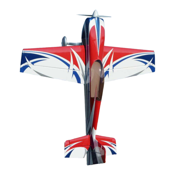
Assembly Manual / Airframe – 108" Extra 330LT
Thank you for purchasing this 3DHobbyShop ARF RC aircraft. If you have any issues,
questions, concerns or problems during assembly, please contact our tech department
at: Info@3DHobbyShop.com or 717-814-5316 10am-4pm Eastern Monday thru
Thursday.
SAFETY in Assembly
During assembly of this aircraft, you will be asked to use sharp knives and hobby
adhesives. Please follow all safety procedures recommended by the manufacturers of
the products you use, and always follow these important guidelines:
ALWAYS protect your eyes when working with adhesives, knives, or tools, especially
power tools. Safety glasses are the best way to protect your eyes.
ALWAYS protect your body, especially your hands and fingers when using adhesives,
knives, or tools, especially power tools. Do not cut toward exposed skin with hobby
knives. Do not place hobby knives on tables or benches where they can roll off or be
knocked off.
ALWAYS have a first-aid kit handy when working with adhesives, knives, or tools,
especially power tools. ALWAYS keep hobby equipment and supplies out of the reach of
children.
SAFETY in Flying
This is NOT a toy! It is a very high-performance RC airplane capable of high speeds and
extreme maneuvers. It should only be operated by a competent pilot in a safe area with
proper supervision.
ONLY fly your aircraft in a safe, open area, away from spectators and vehicles and
where it is legal to fly. NEVER fly over an unsafe area, such as a road or street.
Advertisement

Subscribe to Our Youtube Channel
Related Manuals for 3D Hobby Shop Extra 330LT


Summary of Contents for 3D Hobby Shop Extra 330LT
- Page 1 Assembly Manual / Airframe – 108” Extra 330LT Thank you for purchasing this 3DHobbyShop ARF RC aircraft. If you have any issues, questions, concerns or problems during assembly, please contact our tech department at: Info@3DHobbyShop.com or 717-814-5316 10am-4pm Eastern Monday thru Thursday.
-
Page 2: Limits Of Responsibility
The end user assumes all responsibility and liability in use of 3D Hobby Shop aircraft and components and agreeing to hold harmless 3D Hobby Shop, it's distributors and... -
Page 3: Required Items
REQUIRED ITEMS Hobby Knife Small Phillips Screwdriver Set Metric Allen Wrenches Scissors Small Pliers Wire Cutters Adjustable wrench Masking tape Drill and drill bits Threadlocker (Blue Loctite) Polyurethane and/or 30min epoxy glue Rubbing alcohol Optional – Heat gun and covering iron Dremel tool Assembly Instructions –... -
Page 4: Let's Get Started
application of heat to the covering material on your airplane. The best tools to use are a heat gun and covering iron. Apply the heat gently: the covering material will shrink as you apply the heat, and this will remove the wrinkles. BE CAREFUL! Too much heat applied too quickly can damage the covering, either by causing it to pull away from the wood at seams and corners or even by melting it. - Page 5 Using a soldering iron or hobby knife, remove covering from forward fuselage areas. Front Anti-rotation pin Wing Safety Pin Wingtip( Factory Cut) Aileron servo leads. Wing bolt Rear Anti-rotation pin...
- Page 6 Next remove covering for the front stab carbon tube. Remove tail wheel assembly set screws one at a time and re-torque using blue loctite.
- Page 7 Install tail wheel assembly using 3x-4-40 bolts and washers. Use blue loctite on the bolts.
- Page 8 Contents of landing gear hardware bag. The axles come pre-drilled and the pin is included in the hardware bag. To get the proper spacing you will need 1 collar and one washer on the inside of the axle and then one washer on the outside of the axle as shown.
- Page 9 Take note of the washer and wheel collar as discussed above. Remember to slide the landing gear cuffs on before attaching both wheel pants as well. The screws holes should face towards the ground. The picture above shows the front of...
- Page 10 the gear towards the left of the page. The thicker portion of the cuffs should be towards the rear of the plane as shown above. Insert wheel into wheel pant as shown here. Now attach the assembled wheel and pant to the landing gear with the included #4-40 bolts and nylon lock nut.
- Page 11 Make sure the wheel is centered in the pant. If adjustment is needed, you can rearrange the washers and collar to achieve it.
- Page 12 Next attach the landing gear to the plane with the included 4mm bolts, washers, and nylon lock nuts.
- Page 13 Use the Phillips head 3mm screw to attack the cuffs to the landing gear. The cuffs can also be used to hold the landing gear cover plate in place. Using a 3-32 allen wrench, be sure to make the already installed #4-40 bolts are tight.
- Page 14 The 108” Extra has a long tunnel suitable for canisters or tuned pipes. We provide the parts for a variety of setups. Vented covers are included for the tunnel which can be installed if desired. If using stock mufflers, the covering over the tunnel can be left intact if desired.
- Page 15 Here are the included panels. There are various canister/pipe mounts included, drilling template, throttle servo box, and covers for various places on the airframe. Remove the covering over the vent holes on the cover plates as shown.
- Page 16 Install the cover plates over the canister/pipe tunnel as shown using wood screws. This is a picture from the 104” Slick so the panels may look slightly different.
- Page 17 Your kit includes two different kinds of ball links. The top one is used in between the phenolic control horns. The bottom one, with the integrated spacer, is used on the servo arm end. Pushrods on the 108” Extra are assembled in this way, with a ball link on each end of a stainless-steel link.
- Page 18 Because the links are opposite threaded on each end, you can use the included link wrench in your kit to change the pushrod length after they are installed on the airplane. The control horns on the 108” Extra are the double-phenolic fiberglass style. The horns for the elevators and ailerons are identical.
- Page 19 Elevator and Aileron horns are installed as follows: Using sand paper or something similar, rough up the areas that will be glued as shown.
- Page 20 Locate the two slots and use a single control horn to make sure each of the two slots are cleaned out. Doing so will make installing the fully assembled horn much easier. Assemble the control horn as shown. Temporarily install in the control horn and cut out around the base of it as shown.
- Page 21 covering. Next, glue in the control horn using either 30min epoxy, or Gorilla Glue. This same process is used for the elevators and ailerons. The 108” Extra offers two locations for rudder servos. Pull-pull cables are already installed in the Edge for use with the forward location under the canopy bubble. An alternate rear location is provided at the tail of the airplane.
- Page 22 Installing the rudder control horn: Assemble control horn as shown. Temporarily install the control horn, cut out around the base like we did for the aileron and elevator control horns. You can also use tape around the base that will keep glue from getting on the covering.
- Page 23 Once the glue has set, install the rudder onto the fuse using the included hinge pin.
- Page 24 Install rudder onto vertical stabilizer and fuselage, slide rudder hinge wire into rudder from the top and down into the recess slot on top of rudder as shown. Install collar onto rudder hinge wire at bottom. Trim wire as needed.
- Page 25 Pull-pull cables are already installed into your fuselage. Complete rear end of pull wires on both sides as shown, using double crimps and looping wire through crimps as shown.
- Page 26 Cross the pull-pull wires once inside the fuselage to form an “X” and complete the front end of the cables also with double crimps. A typical servo installation with one 3” double- sided offset arm is shown. Make cables snug, but not “banjo-string” tight. Only snug is necessary.
- Page 27 Install your elevator servo into the horizontal stab of your choice as shown. Yes, this will take some time and you will need a long screwdriver. Be patient.
- Page 28 Parts included in elevator hardware bag. Install the servo arm and linkage as shown. You may want to lengthen the slot depending on which arm you choose to use. A 1.75” arm is used in this picture. Install both carbon stabilizer tubes into fuselage, and slide stabs on all the way. Attach with 4-40 screws and washers as shown.
- Page 29 Included engine mounting hardware...
- Page 30 The lines etched on the firewall match the lines etched on the template. Make sure all of the lines are lined up before drilling. Use tape to hold in place. Hole size is 1/4”...
- Page 31 Use large washers on the back along with the nylon lock nuts. Also shown here is the throttle servo mounted. You can used the included wooden servo rings to give the servo mounting screws more wood to bite into.
- Page 32 The long standoffs plus one washer should give you the desired spinner to cowl gap. An extra washer may need to be added, or this washer can be removed depending on the spinner gap you prefer. DA-100 and DLE-111 mounted with shorter standoffs.
- Page 33 Included throttle linkage parts. NOTE: The link length included is approximate, it works well on DA-100 and DLE-111, for DA-120 which mounts farther forward, you may need a longer link for best geometry. Installing link.
- Page 34 NOTE: A choke servo location is supplied on the bottom of the engine box AND a separate box-type servo mount is included in the kit to allow you to mount a choke servo in any location. However, we use and recommend a simple manual pull-type choke linkage which extends through the bottom of the cowl.
- Page 35 NOTE: The J&A Engineering DA 120 Slick Mufflers sold by 3DHS allow for the cleanest cowl install possible. The front of these mufflers are cut at an angle to allow them to fit in the cowling.
- Page 36 In this build we decided to close off the tunnel and cut cooling slots in the bottom of the cowling.
- Page 37 Here is an example layout of the throttle and fuel line setup. WARNING: make sure that the fuel line cannot come into contact with the muffler. In the picture above, we used flame retardant heat shrink over the tubing just in case it would ever touch the muffler. Next attach the bottom half of the cowling using the included #4-40 screws and washers.
- Page 39 NOTE: There are three servo locations in each wing panel. You can use one servo in the center location, two in the inner and outer locations, or three servos. Be *extremely careful* if using only one aileron servo, most twin-cylinder engines 100CC and up produce enough power to blow back or even a flutter a single aileron servo.
- Page 40 duty metal gear aileron servos per wing. NOTE: Pull Strings are pre-installed in your wing panels to facilitate pulling servo leads through the wing panel.
- Page 41 The wings are attached using a 6mm nylon bolt and spring clip. The first few times you install the wings, the holes for the spring clips will be tight to the fuselage side. This is by design, use a small tool to clearance this fit before installing the clip. After a few cycles this will settle in at the proper clearance.
- Page 42 The canopy hatch is supplied with the floor pre-installed. The rear of the hatch is left open so you can easily install a pilot head and cockpit control panel. When you have completed any work inside the cockpit, use a small amount of CA glue to install the balsa rear plate onto the canopy hatch.
- Page 43 The preferred CG for this plane is at 4.5” back from the leading measured at the wingtip. This is the recommended CG to start with and can then be tuned for a specific style of flying. 3D Hobby Shop wishes you the very best with your new 108” Extra!
Need help?
Do you have a question about the Extra 330LT and is the answer not in the manual?
Questions and answers