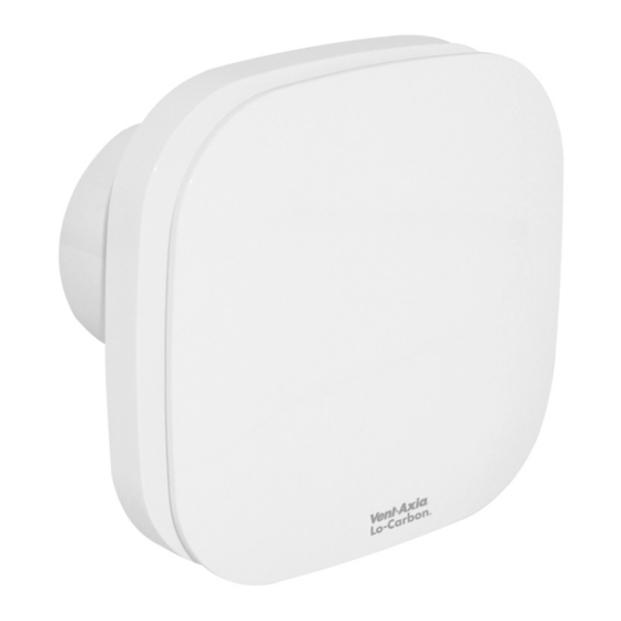
Summary of Contents for Vent-Axia NBR HTP 473809
- Page 1 CONTINUOUSLY RUNNING FAN Installation and Wiring Instructions Stock Ref. N° NBR HTP 473809 220-240V~50Hz IPX4 PLEASE READ INSTRUCTIONS IN CONJUNCTION WITH ILLUSTRATIONS. PLEASE SAVE THESE INSTRUCTIONS.
-
Page 2: Safety And Guidance Notes
C. Ensure that the mains supply (Voltage, Frequency, and Phase) complies with the rating label. D. The Fan should only be used in conjunction with the appropriate Vent-Axia products. E. The fan should only be used in conjunction with fixed wiring. -
Page 3: Wall Mounting
A. INSTALLATION PANEL/CEILING MOUNTING Cut a 105mm diameter hole. Remove the front panel by carefully pulling away from the fan. Loosen the two self-retaining screws and remove the inner grille by carefully pulling away from the housing. Mark the screw centres through the holes in the fan back plate. Drill, plug and screw into position. - Page 4 C. SETUP WARNING: THE FAN AND ANCILLARY CONTROL EQUIPMENT MUST BE ISOLATED FROM THE POWER SUPPLY DURING THE INSTALLATION / OR MAINTENANCE. 1) Trickle speed selection (6l/s or 8l/s) – (Fig. 5) In normal running mode the fan can extract at either 6l/s (22m /h) or 8l/s (29m flow rate.
- Page 5 5) Adjustable ambient Response humidistat The HTP model incorporates an adjustable ambient response humidistat. The fan will increases the extract rate if the humidity rises above the set point – adjustable via the pot shown in fig. 5. To RAISE the set-point use a small screwdriver to turn the adjuster Fig.5. ANTICLOCKWISE.
-
Page 6: Servicing And Maintenance
iii. When the LS is connected, the fan will run at 13l/s until deactivated (plus overrun timed period where applicable). b. Dip switch 2 in the on position: i. Standard running – with the LS off, pullcord off. Fan continues to run on the set trickle speed - 6 or 8l/s. - Page 7 ii. The humidity set point is set too low. b. Solution: i. If the room is damp or has recently been decorated, it could take up to 2 weeks for the humidity levels to stabilise. Please leave the fan to dry out the room and after this period the fan should run normally.
- Page 8 Siting fan. Fig.1 Continuous trickle (6l/s or 8l/s) with no boost facility. (The fan is internally fused) Fig.2 Continuous boost (13l/s) with no trickle facility. (The fan is internally fused) Fig.3 Continuous trickle with boost facility. (The fan is internally fused)
- Page 9 Fig.4. Removing the grille for wiring and setting the controls Pull front panel as shown. Loosen screws – DO NOT REMOVE FROM GRILLE (the screws are self-retaining) Pull inner grille away from housing as shown. When replacing grille, ensure the flow sensor is aligned with the corresponding slot in the grille.
- Page 10 Fig. 6. Display and prism The display can only be seen from the side. This is to allow the installer to view the display with the cover attached as this can affect the airflow through the sensor. Every 10-20 seconds the display will switch between displaying airflow rate and system pressure. The system pressure will flash.
- Page 12 Vent-Axia guarantees its products for two years from date of purchase against faulty material or workmanship. In the event of any part being found to be defective, the product will be repaired, or at the Company’s option replaced, without charge, provided that the product:- ...


Need help?
Do you have a question about the NBR HTP 473809 and is the answer not in the manual?
Questions and answers