
Related Manuals for Vent-Axia HR400


Summary of Contents for Vent-Axia HR400
- Page 1 Please leave these instructions with the user HR320 & HR400 Whole House Ventilation System With Heat Recovery Installation and Servicing Instructions HR400 HR320...
-
Page 3: Table Of Contents
Contents Section Page Introduction Site Requirements Installation Electrical Commissioning Servicing Fault Finding Guarantee... -
Page 4: Introduction
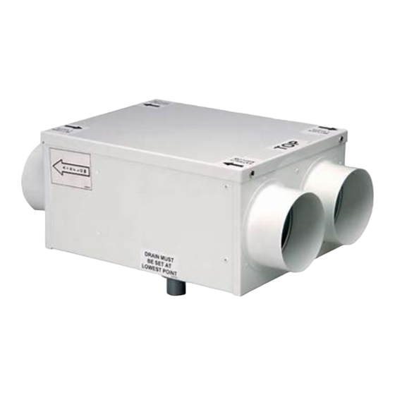
1.0 Introduction Description 1. The HR320 and HR400 are a range of whole house ventilation units (Figs. 1 & 2). The ventilation unit works in conjunction with a duct system enabling air to be transferred throughout the house. The whole house system works by replacing the warm stale moist air from the house, with fresh air from outside. -
Page 5: Site Requirements
2.0 Site Requirements Information 1. The fan unit is to be permanently connected to the mains electrical supply and must be installed by a suitably qualified person. 2. The fan unit must be sited and connected in accordance with UK Building and IEE Wiring Regulations (BS 7671) or regulations and /or standards appropriate to the country of use. - Page 6 2.0 Site Requirements Information (cont) 10. The external grilles/terminals for the system must be sited at least 1m away from the flue of a fuel burning appliance, in compliance with the requirements of Local Authority, Building Regulations and any other relevant Codes of Practice.
-
Page 7: Installation
3.0 Installation Installing the Fan Unit HR400 1. Check the diagrammatic ducting layout drawing to ensure that the proposed duct routes, fan unit and air terminal locations can be accomodated. If in doubt refer to the Technical Department. 2. The units are suitable for either vertical or horizontal mounting. - Page 8 3.0 Installation Installing the Fan Unit (cont) Horizontal Mounting (Fig. 7) 7. Before installation of the fan unit, a wooden Top Cover platform must be provided to mount the unit on. 8. The platform should be constructed from 50mm x 100mm timber bearers with a 19mm block board deck.
- Page 9 3.0 Installation Installing the Fan Unit (cont) HR400 Vertical Mounting HR400 (Fig. 8) 12. The HR400 can be mounted vertically by securing with plugs and screws through the casing (see horizontal mounting). Vertical Mounting HR320 The HR320 is supplied with a wall mounting kit.
- Page 10 3.0 Installation Supply and Extract Air Terminals SV100 / EV100 Installing the Ducting System 1. Cut off the closed ends of the duct spigots that are to be connected to the duct system. Terminal Housing Ensure that no cutting debris falls into, or remains in the unit as this could damage the balanced impellers and cause excessive noise Plaster Board...
- Page 11 3.0 Installation Installing the Ducting System (cont) 7. The external grilles for intake and exhaust air should be positioned so that the exhaust air is not drawn in again. 8. If the grilles are fitted in the same gable at the same height, a minimum of 1m between grilles is recommended.
- Page 12 3.0 Installation Installing the Ducting System (cont) 18. The quantity and location of flexible silencers (FS100), if required, will depend upon total airflow rate. If in doubt check with the Technical Department. These should be installed between the unit and the first supply/extract terminal on the duct system, to reduce the noise from the unit, which would otherwise be transmitted through the duct system and into the home.
- Page 13 3.0 Installation Installing the Ducting System (cont) 25. A pack of pre-insulated flexible ducting (IFD100) is included with the kit together with worm drive clips (FC180). The flexible ducting is intended for use in making the final connection between the rigid ducting and the external wall/soffit grilles or roof ventilators.
- Page 14 3.0 Installation Installing the Ducting System (cont) 35. The rectangular system of ducting, white rigid UPVC, permits fast, easy assembly and is normally used in flatted accomodation. This ducting can be surface mounted internally where a ceiling void is not available, fitted between ceiling and floor between joists, or when a ceiling void is not accessible or too small to work in.
- Page 15 3.0 Installation Installing the Ducting System (cont) 42. Rectangular ducting can be concealed in a suspended ceiling having a minimum clearance of 76mm (double battening) between the ceiling and the plasterboard. This allows the use of ceiling mounted supply (SV100) and extract (EV100) valves utilising the 90°...
- Page 16 3.0 Installation Installing the Ducting System (cont) 47. A variety of push fit white rigid UPVC fittings are available. 48. Integral grilles and louvres provide attractive extract and supply for low cost installations. Tube and fittings are manufactured in flame retardant plastics to DIN4102/B1.
-
Page 17: Electrical
4.0 Electrical Wiring Options VCON7 and NBSW / VCON100 Manual Normal to Boost Speed Control Mains Via 3A Fused Spur Unit Normal/Boost VCON77 Switch Select appropriate VCON77 tapping for NORMAL speed setting VCON7 and HS6 Automatic Normal to Boost Speed Switching Mains Via 3A Fused Spur Unit... -
Page 18: Commissioning
5.0 Commissioning Commissioning the System Filter (optional) Before starting to commission the system check that the crossflow heat exchanger and the filter Electrical Plug panel (if ordered) are properly and securely in place (Fig. 16). Check that all sockets are Cover correctly engaged, that the wiring is secure and properly mounted and that the unit cover is... - Page 19 5.0 Commissioning Commissioning the System (cont) 8. Standard ceiling terminals type EV100 and SV100 are adjusted by turning the central screw and are locked in the “set” position by the locknut. 9. Move to the next terminal down the line and adjust as before.
-
Page 20: Servicing
6.0 Servicing Annual Servicing 1. As well as providing fresh pre-warmed air the system also removes odours, moisture, excessive heat and airborne impurities such as Cover dust, dirt and grease. These impurities gradually build up and detract from the efficiency of the heat exchanger. 2. -
Page 21: Fault Finding
7.0 Fault Finding Fault Cause Remedy Fault Cause Remedy 1. Unit will not Electrical Fault Switch off the mains 4. Low airflows at 1) VCON77 1) Increase voltage operate when electrical supply to terminal devices controller set at setting at VCON77 switched on. -
Page 22: Guarantee
8.0 Guarantee Guarantee This guarantee is offered to you as an extra benefit and does not effect your legal rights. The products are guaranteed for one year from date of purchase against faulty materials or workmanship. In the event of any part found to be defective, providing that: 1. - Page 24 370712 - Iss B - 06/04 Comp N VENT-AXIA Ltd FLEMING WAY CRAWLEY WEST SUSSEX RH10 9YX www.vent-axia.com...
Need help?
Do you have a question about the HR400 and is the answer not in the manual?
Questions and answers