MSA FireHawk M7 Upgrade Instructions
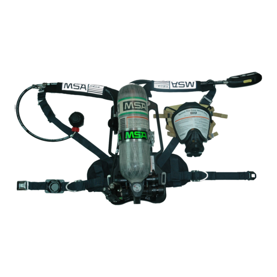
Air mask
Hide thumbs
Also See for FireHawk M7:
- Operation and instructions manual (56 pages) ,
- User manual (45 pages) ,
- Maintenance and repair (12 pages)
Table of Contents
Advertisement
Quick Links
FireHawk
Air Mask
NFPA 1981 - 2007 Edition Compliant
UPGRADE INSTRUCTIONS
This manual must be carefully read and followed by all persons who have, or will
have, the responsibility for upgrading this air mask. This air mask will perform as
designed only if upgrading according to the instructions. Otherwise it could fail to
perform as designed, and persons who rely on the air mask could sustain serious
personal injury or death.
DO NOT use a 2216psi air cylinder on a 3000psi operating system. Such a configuration
is not approved by NIOSH. Failure to follow this warning can result in serious personal
injury or death.
The FireHawk M7 Control Module, Power Module, and HUD Receiver comply with
Part 15 of the FCC Rules.
Operations are subject to the following conditions:
(1)
This device may not cause harmful interference and
(2)
This device must accept any interference that may cause undesired
operation.
Changes and modifications not expressly approved by the manufacturer could void the
User's authority to operate the equipment.
The warranties made by MSA with respect to the product are voided if the product is not
installed, used and serviced in accordance with the instructions in this manual. Please pro-
tect yourself and your employees by following the instructions. Please read and observe the
WARNINGS and CAUTIONS inside. For any additional information relative to use or repair,
write or call 1-800-MSA-2222 during regular working hours.
TAL 808 (L) Rev. 1
M7
®
© MSA 2008
Prnt. Spec. 10000005389(A)
Mat. 10090073
Doc. 10090073
Advertisement
Table of Contents

Related Manuals for MSA FireHawk M7


Summary of Contents for MSA FireHawk M7
- Page 1 Changes and modifications not expressly approved by the manufacturer could void the User’s authority to operate the equipment. The warranties made by MSA with respect to the product are voided if the product is not installed, used and serviced in accordance with the instructions in this manual. Please pro- tect yourself and your employees by following the instructions.
-
Page 2: Table Of Contents
Do not alter, modify, or substitute any components with- out the approval of the manufacturer. Such alterations will Prior to installation of the FireHawk M7 Upgrade Kit, the void the NIOSH approval. air mask must be upgraded to be compliant with the 2002 Edition of the NFPA-1981 Standard. -
Page 3: Inspection And Functional Test Of The 2002 Nfpa Compliant Air Mask
Check the high pressure hose between the Audi- the FireHawk M7 Upgrade Kit. Used, worn, or dam- Larm Audible Alarm and the first stage regulator. aged parts can result in serious personal injury or Look for cuts or severe abrasions. -
Page 4: Cylinder Inspection
Slide-to-Connect Ultra Elite Facepiece, the following com- ponents must be installed: 10018621 Slide-to-Connect Inlet Adapter Note: Aluminum and steel cylinders are not approved for 10034500 Slide-to-Connect Facepiece Cover use with the FireHawk M7 Air Mask. 10033208 Screws 490134 Spider Gasket 491933 Inlet Disc... - Page 5 INTRODUCTION assembly opening. Once the release is lifted, remove the cover by pulling it away from the hous- ing. Tilt the cover and work it over one adapter bay- onet at a time. b. For the Firehawk Slide-To-Connect Regulator: Remove the cover by pulling it away from the hous- ing.
- Page 6 NOTES TAL 808 (L) Rev. 1 - 10090073...
-
Page 7: Converting The Facepiece From ¼ Turn Mmr To Firehawk Regulator
4. Remove the mounting bracket and discard. 5. Reinstall the component housing cover. Installation of the new Firehawk M7 HUD Mounting 6. Check alignment and tighten screws Bracket to the facepiece 1. Slide the new bracket assembly onto the facepiece. -
Page 8: Firehawk Adapter And Cover Installation
Note: If necessary, use a seal. Follow the Facepiece Fit Check procedures in small slot head screwdriver the FireHawk M7 Air Mask Operation and Instruction to engage the cover. Manual (P/N 10082858). 5. Place the neck strap brackets into the sockets (optional). -
Page 9: Installation Of Facepiece Model Number Labels
MN2400, or Duracell Pro Cell MN2400 alkaline batter- the model number described below, a new model number ies in the FireHawk M7 HUD. Use of other batteries, or label must be applied to the facepiece. New CBRN compli a combination of batteries from different manufactur-... -
Page 10: Salvaging Parts From The Current Carrier And Harness
Vulcan Carrier and Harness Assembly, the rubber grommets located on the slots of the carrier are not need- 3. Pull the first stage ed for use on the FireHawk M7 Air Mask. Remove the intermediate pressure components from the webbing and discard. -
Page 11: Removing The First Stage Regulator From The Carrier And Harness
UPGRADE INSTRUCTIONS 5. Save the left shoulder strap for use later. 805010 first stage regulator cap 10052743 model number labels If the current air mask has a 1/4 turn MMR second stage regulator 1. Remove the left pull strap from shoulder strap buckle. 2. -
Page 12: High Pressure Gauge Hose Upgrade
For Air Masks WITHOUT Shoulder Mounted Quick-Fill System Air masks that do not have a shoulder mounted quick-fill may reuse the same hose on the FireHawk M7 Air Mask. A new model number ID tag must be installed on the high 3. Thread the relief valve pressure hose. -
Page 13: Installing Soft Goods On The Carrier And Harness Assembly
UPGRADE INSTRUCTIONS Installing a New Hose on the PR14 First Stage Regulator 2. Pull the hose firmly to remove it from the regulator body. 3. Discard the high pressure hose. Installing the new High Pressure Gauge Hose Removing the PR-14 First Stage Regulator from the 1. - Page 14 UPGRADE INSTRUCTIONS Attaching the waist belt pull straps to the shoulder straps 2. Tug on the shoulder strap to test the attach- 1. Lace the free end of ment. the pull-strap through the friction buckle. Attaching the waist belt to the Carrier 1.
-
Page 15: Installing The Firehawk M7 Control Module
5. Lace the strap through the slide buckle. INSTALLING THE FIREHAWK M7 CONTROL MODULE Note: If the air mask being upgraded does not have the Quick-Fill system, the following steps pertaining to installing the quick-fill adapter may be skipped. - Page 16 UPGRADE INSTRUCTIONS Installing the Quick-Fill Adapter 1. Place the Quick-Fill Adapter block in a vise. This is attached to the M7 Control Module. Use protective sleeves to keep from damaging the block. 2. Wrap the coupling threads with transpar- ent tape to prevent 2.
- Page 17 UPGRADE INSTRUCTIONS 4. Connect the high pressure hose to the Control Module. Note: If equipped with a Quick-Fill system, connect the 2. Hand tighten the con- high pressure hose to the Quick-Fill manifold. a. Use a torque wrench and 9/16” crow foot to tighten nector until the o-ring is the connector to 100-125 in lbs.
-
Page 18: Installing The Firehawk M7 Power Module
10047529 Firehawk MMR with PTC inlet and quick- connect intermediate pressure hose Note: These CBRN compliant Firehawk Regulators are also approved for use on the FireHawk M7 Air Mask: a. Position the Cylinder 10043892, 10043893, 10043894, and 10043895. Stop over the Power Module. -
Page 19: Leak Testing
FUNCTIONAL TEST Before using the air mask, refer to the “visual inspection 5. Use a torque wrench and functional test” section of the Firehawk M7 Operation and 7/16” socket to and Instruction Manual (P/N10082858). tighten the bolts to 35 ±5 in lbs. -
Page 20: Flow Test Requirements
1. The air mask must be flow tested following the upgrade procedures and on an annual basis. 2. The air mask must be tested on a Biosystems Posicheck 3 using the MSA Pro-Check 3 Software. The following tests should be performed: a. Visual Inspection b.
Need help?
Do you have a question about the FireHawk M7 and is the answer not in the manual?
Questions and answers