MSA FireHawk M7 Operation And Instructions Manual
Air mask
Hide thumbs
Also See for FireHawk M7:
- User manual (45 pages) ,
- Upgrade instructions (20 pages) ,
- Maintenance and repair (12 pages)
Table of Contents
Advertisement
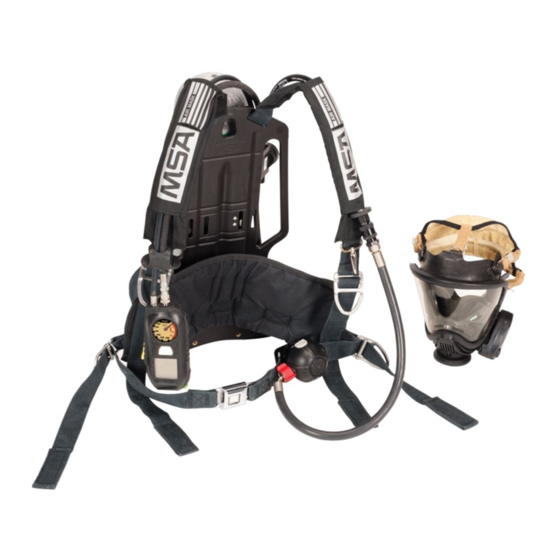
FireHawk
Air Mask
OPERATION AND INSTRUCTIONS
This manual must be carefully read and followed by all persons who have or will have the responsibility for using
or servicing this air mask. This air mask will perform as designed only if used and serviced according to the instruc-
tions; otherwise it could fail to perform as designed, and persons who rely on the air mask could sustain serious
personal injury or death.
This Self-Contained Breathing Apparatus (SCBA) is certified by the National Institute of Occupational Safety and Health
(NIOSH).
This device complies with Part 15 of the FCC Rules. Operation is subject to the following conditions:
(1) This device may not cause harmful interference and (2) this device must accept any interference that may cause
undesired operation.
Changes and modifications not expressly approved by the manufacturer could void the user's authority to operate the
equipment.
The warranties made by MSA with respect to the product are voided if the product is not installed, used and serviced in
accordance with the instructions in this manual. Please protect yourself and your employees by following the instructions.
Please read and observe the WARNINGS and CAUTIONS inside. For any additional information relative to use or repair,
write or call 1-800-MSA-2222 during regular working hours.
TAL 1705 (L) Rev. 18
M7
®
© MSA 2017
Prnt. Spec. 10000005389(A)
Mat. 10082858
Doc. 10082858
Advertisement
Table of Contents

Subscribe to Our Youtube Channel
Related Manuals for MSA FireHawk M7


Summary of Contents for MSA FireHawk M7
- Page 1 The warranties made by MSA with respect to the product are voided if the product is not installed, used and serviced in accordance with the instructions in this manual. Please protect yourself and your employees by following the instructions.
-
Page 2: Table Of Contents
Safety rating and may affect the Intrinsic-Safety of the Office, Washington, DC 20402. Compressed Gas device. Misuse or abuse of the FireHawk M7 HUD or I- Association, Inc., 1725 Jefferson Davis Hwy., Suite 1004, HUD, FireHawk M7 Control Module, FireHawk M7 Power Arlington, VA 22202. - Page 3 Never mine proper facepiece size prior to using the respira- remove the facepiece except in a safe, non-haz- tor. A Fit Test Kit (MSA P/N 10044576) is available for ardous, non-toxic atmosphere. conducting quantitative fit tests with the Ultra Elite 6.
- Page 4 An overhaul kit (MSA P/N 10048942) is available. CONTACT INFORMATION In the event of a product concern, contact your local MSA authorized repair center or distributor, who will provide the necessary information to MSA for issue resolution. To...
-
Page 5: Description
[Title 42 CFR, Part 84.2, (Q)]. There are also two types of Firehawk Regulator intermedi- The FireHawk M7 Air Mask consists of the following ate pressure hose connections, threaded and quick-con- components. - Page 6 530 psi The FireHawk M7 I-HUD performs the same functions as 30 min. 3000 psi 10 minutes 750 psi the FireHawk M7 HUD but it is located inside the Ultra 30 min. 4500 psi 7 minutes 1125 psi Elite Facepiece.
- Page 7 Incident Command. The radio transmit- RESCUE BELT AND RESCUE BELT II ter is located inside of the FireHawk M7 Power Module. The FireHawk M7 Telemetry Module is only available for The MSA Fire Service Rescue Belt and Rescue Belt II are air masks with integrated PASS devices.
- Page 8 NOTES TAL 1705 (L) Rev. 18 - 10082858...
-
Page 9: Inspection And Functional Tests
OFF. 4. Firehawk Second Stage Regulator DO NOT inspect the air mask before cleaning if there a. If the FireHawk M7 Air Mask is equipped with a is danger of contacting hazardous contaminants. quick-connect second stage intermediate pressure Clean and disinfect first, then inspect. Failure to follow... - Page 10 13. FireHawk M7 Power Module (integrated PASS version) minum cylinder service life is indefinite if proper inspec- a. Inspect the FireHawk M7 Power Module housing for tion and hydrostatic test procedures are followed and they external cracks and ensure that the FireHawk M7 indicate that the cylinder may remain in service.
- Page 11 Also verify that the orange NOTE: Firehawk Regulator functional checks must be LED is displayed in the FireHawk M7 HUD or I- conducted with a full cylinder. Check the pressure gauge HUD. Ensure that the FireHawk M7 Control on the cylinder valve to verify that the cylinder is full.
- Page 12 1050 psi - approximately (4500 psi system) 10. Disconnect the Firehawk Regulator from the facepiece. A flashing red LED must display in the FireHawk M7 HUD 11. Close the cylinder valve fully. or I-HUD at the appropriate pressure listed above. The 12.
-
Page 13: Quick-Fill And Urc Coupling Inspection
QUICK-FILL AND URC COUPLING INSPECTION 3. Put the dust cover on the coupling. 4. Grasp the dust cover by hand and, using maximum effort, attempt to loosen the coupling at the joint by turning the dust cover counterclockwise. Do not use 5. - Page 14 NOTES TAL 1705 (L) Rev. 18 - 10082858...
-
Page 15: Donning
FireHawk M7 Power Module (integrated 5. Bend forward slightly; resting the carrier on the back. PASS version) fails to sound, or the FireHawk M7 HUD 6. Attach the chest strap buckle (optional). or I-HUD fails to light, The air mask must be checked 7. - Page 16 DO NOT use the air mask if the Audi-Larm Alarm fails to ring or fails to continuously ring down to pressures of 200 psi, or if the FireHawk M7 Control Module (inte- grated PASS version) or FireHawk M7 HUD or I-HUD fails to light properly.
- Page 17 4. Listen for any hissing or popping sounds from the Audi-Larm Alarm. If heard, return the air mask to an MSA trained or certified repairperson. FACEPIECE FIT CHECK NOTE: Check the inhalation valve by inhaling. If the face- piece does not provide sufficient flow of air, do not use facepiece.
- Page 18 A regulator that is not installed correct- pushing inward. ly can separate from the facepiece unexpectedly. Return the air mask to an MSA trained or certified repairperson to correct the condition. Misuse can result in serious injury or death.
- Page 19 DONNING NOTE: If the air mask passes all tests, it is ready for use. These tests must be performed every time before entering a hazardous atmosphere. If the air mask fails to meet any of the tests, the condition(s) must be corrected before using the air mask.
- Page 20 NOTES TAL 1705 (L) Rev. 18 - 10082858...
-
Page 21: Using The Air Mask
NightFighter HUD Transmitter. Module (integrated PASS version), and Audi-Larm Alarm indicate when cylinder pressure drops below these 1. The FireHawk M7 HUD or I-HUD allows the user to approximate values: see the cylinder pressure while the air mask is in use. - Page 22 Batteries in the FireHawk M7 HUD or I-HUD. LED, and this LED will extinguish when full PASS alarm has been reached or the pre-alarm has been Refer to Chart 1 for a full description of all FireHawk M7 reset. HUD LED patterns.
- Page 23 Red and Orange Left Side LED Flashing Alternating Replacing the Batteries in the FireHawk M7 HUD in the FireHawk M7 HUD. Use of other batteries, or a combination of batteries from different manufacturers, will affect the performance of unit and void the Intrinsic Safety Approval.
- Page 24 With the facepiece lying on its side: TRANSMITTER. Use of other batteries, or a combina- 1. Align the metal tab on the FireHawk M7 HUD with the tion of batteries from different manufacturers will void TAL 1705 (L) Rev. 18 - 10082858...
- Page 25 USING THE AIR MASK metal plate on the front edge of the bracket. 2. Rotate the FireHawk M7 HUD so that the tab falls into DO NOT use a screwdriver to tighten the thumbscrew. the slot behind the thumbscrew. 3. Thread the thumbscrew into the tab to finger-tight.
- Page 26 The FireHawk M7 Control Module is assembled to the vide adequate I-HUD retention friction on the nosecup gauge line hose and is connected to the FireHawk M7 assembly. The friction is generated by the I-HUD Power Module by the power cable. The FireHawk M7...
- Page 27 FireHawk alarm button on the FireHawk M7 Control Module. M7 Control Module display will flash and the FireHawk M7 • The PASS function uses red and green LEDs behind Power Module will sound a tone every 3 seconds.
- Page 28 Actual time remaining may be less than the calculated time displayed. Increases in breathing rate may reduce 1. If there is a low battery in the FireHawk M7 HUD or I- remaining time more than expected. Use time indica- HUD, one yellow LED will flash in the FireHawk M7 tor as general guide only.
- Page 29 Use only Rayovac 814 or AL-C (Regular/Max or second. Ultrapro), Duracell MN1400, or Duracell Procell PC1400 a. The FireHawk M7 Power Module will beep once when alkaline batteries in the FireHawk M7 Power Module. the reset button is pressed once. Pressing the reset...
- Page 30 NOTES TAL 1705 (L) Rev. 18 - 10082858...
-
Page 31: Cold Weather Operation
Prior to storage of the air mask at temperatures below 0˚F, NOTE: Fresh batteries must be installed in the FireHawk verify that the FireHawk M7 Power Module, FireHawk M7 M7 HUD or I-HUD, FireHawk M7 Power Module, and HUD, and FireHawk M7 I-HUD are equipped with full NightFighter HUD Transmitter prior to storage of the Air charge batteries. - Page 32 NOTES TAL 1705 (L) Rev. 18 - 10082858...
-
Page 33: Urc Assembly
NIOSH approvals of exceeds 2216 psi a relief valve in the URC Assembly SCBA from MSA are maintained while transfilling air only if will vent at approximately 2525 psi or as low as 2400 appropriate hose assemblies from MSA are used. URC psi. - Page 34 After approximately 45-60 seconds, the pressure between the secondary air supply and the air mask 1. If the donor's alarm is not ringing and FireHawk M7 cylinder will be equal. HUD or I-HUD/FireHawk M7 Control Module (integrat-...
- Page 35 AUDI-LARM ALARM WITH URC ASSEMBLY pop may be heard as the fittings separate and the b. If the hose will not reconnect, reach behind and high pressure air is sealed off. close the cylinder valve. Air pressure in the regulator g.
-
Page 36: Removing The Apparatus
(yellow) two times within approximately one second. NOTE: FireHawk M7 HUD or I-HUD will automatically turn itself OFF, approximately 60 seconds after the air mask has been depressurized. (The red LED will flash until the 1. - Page 37 REMOVING THE AIR MASK belt buckle release button IN. NOTE: Be sure to completely tighten the latch wing each 8. Disconnect the chest strap buckle (if used). time a cylinder is installed. 9. To loosen the shoulder straps, grasp the pull tabs and push them out and away from the body.
- Page 38 Level (grade) D air or equivalent specification. In the latest retest date may be recharged to a pressure, i.e. fire service applications, MSA recommends breath- a cylinder stamped 3AA2015 with a plus (+) sign after the ing air quality in accordance with NFPA 1989.
- Page 39 Store the units in a cool, dry place. NOTE: Fresh batteries must be installed in the FireHawk M7 HUD or I-HUD, FireHawk M7 Power Module, and NightFighter HUD Transmitter prior to storage of the Air Mask at cold temperature for an extended period of time.
- Page 40 NOTES TAL 1705 (L) Rev. 18 - 10082858...
-
Page 41: Cleaning And Disinfecting
Remove the mask mounted regulator from the face- piece. f. FireHawk M7 Chest Mounted Pressure Gauge and b. Remove the FireHawk M7 HUD or I-HUD. For the LCD Cover Lens FireHawk M7 HUD, unthread the thumb screw and g. First Stage Regulator (PR14) remove it from the facepiece bracket. - Page 42 NOTES TAL 1705 (L) Rev. 18 - 10082858...
-
Page 43: Flow Test And Overhaul Requirements
FLOW TEST AND OVERHAUL REQUIREMENTS FLOW TEST AND OVERHAUL REQUIREMENTS MSA air masks must be flow tested every year using an MSA approved flow test device. The following table sum- The Firehawk Regulator and Audi-Larm Alarm must be marizes MSA’s required frequency for overhaul and flow flow tested and overhauled at specific time intervals. - Page 44 NOTES TAL 1705 (L) Rev. 18 - 10082858...
-
Page 45: Quick-Fill System
1. The Quick-Fill System can only be used to fill these instructions, cautions, and warnings. NIOSH approved air mask cylinders. approvals of SCBA from MSA are maintained while trans- 2. The Quick-Fill System is not to be used as a "Buddy filling air ONLY if appropriate quick-fill hose assemblies Breather"... - Page 46 Push the female fitting of the hose onto the male 1. If the donor's alarm is not ringing and FireHawk M7 quick-fill fitting until it snaps in place. Pull on the HUD or I-HUD/FireHawk M7 Control Module (integrated hose to be sure the connection is secure.
- Page 47 QUICK-FILL SYSTEM air is leaking: a. Immediately reconnect the quick-fill hose to seal off the leak and return to fresh air. b. If the hose will not reconnect, reach behind and close the cylinder valve. Air pressure in the regulator will drop, and the leak will slow down.
- Page 48 NOTES TAL 1705 (L) Rev. 18 - 10082858...
-
Page 49: Extendaire Systems
DO NOT install or attempt to use any hose assembly Use this emergency escape breathing system for life or fitting other than those supplied by MSA for the threatening emergencies and simulated training exer- ExtendAire System. Misuse can result in serious injury cises only. -
Page 50: Extendaire Systems, Airline Attachment Option
2. Replace the dust cap on the Snap-Tite plug. tus, the device shall be supplied with respirable air through 8 to 300 feet of MSA air supply hose within the pressure ExtendAire II System Connection Procedure range of 85-90 psig. - Page 51 DO NOT install or attempt to use any hose assembly EMERGENCY OPERATION or fitting other than those supplied by MSA for the ExtendAire I System. Misuse can result in serious per- If the airline supply should fail for any reason as detected sonal injury or death.
- Page 52 Hose sections vary from 8 ft. to 100 ft. lengths. Airline connection to the apparatus ALTERNATIVE COUPLERS is to be made through an MSA P/N 467044 quick-discon- nect only. The ExtendAire I Adapter Hose Kit may be modified to use the following plugs: 2.
-
Page 53: Firehawk M7 Telemetry Module
When the FireHawk M7 Telemetry Module is used with the receive an evacuation signal from the remote base FireHawk M7 Air Mask, an ID Tag is used to assign a fire- station after it has been successfully logged on to the fighter’s name to the air mask. - Page 54 PC screen. DO NOT use the tag to press the mode button, place it on top of the FireHawk M7 Control Module, or next to NOTE: The air mask must the FireHawk M7 Control Module. The tagging instruc-...
- Page 55 Logging the Air Mask on to the Base Station final confirmation signal. 1. Turn on the FireHawk M7 Control Module on by open- Evacuation Signal ing the cylinder valve or by pressing and holding the If the air mask is logged on to the base station, the inci- alarm button.
Need help?
Do you have a question about the FireHawk M7 and is the answer not in the manual?
Questions and answers