Table of Contents
Advertisement
Available languages
Available languages
Quick Links
User & installation manual
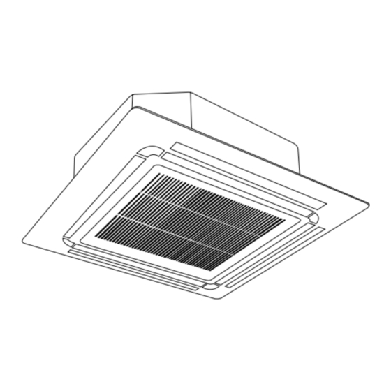
FOUR-WAY CASSETTE T YPE AIR CONDITIONER
CFMD R410A
Multilingual Manual
(English- French)
CFMD-035N-01M25/YFAD-035R-01M25
CFMD-050N-01M25/YFAD-050R-01M25
CFMD-070N-01M25/YFAD-070R-01M25
CFMD-100N-01M25/YFAD-100R-01T35
CFMD-140N-01M25 /YFAD-140R-01T35
IMPORTANT NOTE:
Read this manual carefully before installing or operating your new air conditioning unit. Make sure to
save this manual for future reference.
21.AW.CFMD.035-140.R410A.UM+IM.EN.FR.10.20
Advertisement
Chapters
Table of Contents

Related Manuals for Airwell CFMD-035N-01M25


Summary of Contents for Airwell CFMD-035N-01M25
- Page 1 User & installation manual FOUR-WAY CASSETTE T YPE AIR CONDITIONER CFMD R410A Multilingual Manual (English- French) CFMD-035N-01M25/YFAD-035R-01M25 CFMD-050N-01M25/YFAD-050R-01M25 CFMD-070N-01M25/YFAD-070R-01M25 CFMD-100N-01M25/YFAD-100R-01T35 CFMD-140N-01M25 /YFAD-140R-01T35 IMPORTANT NOTE: Read this manual carefully before installing or operating your new air conditioning unit. Make sure to save this manual for future reference.
- Page 2 User & Installation Manual FOUR-WAY CASSETTE TYPE AIR CONDITIONER CFMD R410A English Manual CFMD-035N-01M25/YFAD-035R-01M25 CFMD-050N-01M25/YFAD-050R-01M25 CFMD-070N-01M25/YFAD-070R-01M25 CFMD-100N-01M25/YFAD-100R-01T35 CFMD-140N-01M25/ YFAD-140R-01T35 IMPORTANT NOTE: Read this manual carefully before installing or operating your new air conditioning unit. Make sure to save this manual for future reference.
-
Page 3: Table Of Contents
Table of Contents Safety Precautions ................04 Owner’s Manual Unit Specifications and Features ............08 1. Indoor unit display................................08 2. Operating temperature..............................10 3. Other features ..................................11 Care and Maintenance ..............12 Troubleshooting ................14... - Page 4 Installation Manual Accessories ...................17 Installation Summary ................18 Unit Parts ....................19 Indoor Unit Installation ...............21 1. Select installation location..............................21 2. Hang indoor unit..................................23 3. Drill wall hole for connective piping..........................25 4. Connect drain hose...................................26 Outdoor Unit Installation................ 1. Select installation location..............................28 2.
-
Page 5: Safety Precautions
Safety Precautions Read Safety Precautions Before Operation and Installation Incorrect installation due to ignoring instructions can cause serious damage or injury. The seriousness of potential damage or injuries is classified as either a WARNING or CAUTION. CAUTION WARNING This symbol indicates the possibility of This symbol indicates the possibility property damage or serious consequences. - Page 6 CLEANING AND MAINTENANCE WARNINGS Turn o the device and disconnect the power before cleaning. Failure to do so can cause • electrical shock. Do not clean the air conditioner with excessive amounts of water. • Do not clean the air conditioner with combustible cleaning agents. Combustible cleaning agents •...
-
Page 7: Owner's Manual
WARNINGS FOR PRODUCT INSTALLATION 1. Installation must be performed by an authorized dealer or specialist. Defective installation can cause water leakage, electrical shock, or re. 2. Installation must be performed according to the installation instructions. Improper installation can cause water leakage, electrical shock, or re. (In North America,installation must be performed in accordance with the requirement of NEC and CEC by authorized personnel only.) 3. - Page 8 European Disposal Guidelines This marking shown on the product or its literature, indicates that waste electrical and eletrical equipment should not be mixed with general household waste. Correct Disposal of This Product (Waste Electrical & Electronic Equipment) This appliance contains refrigerant and other potentially hazardous materials. When disposing of this appliance, the law requires special collection and treatment.
-
Page 9: Unit Specifications And Features
Unit Specifications and Features Indoor unit display NOTE: Di erent models have di erent display panel. Not all the indicators describing below are available for the air conditioner you purchased. Please check the indoor display panel of the unit you purchased. Illustrations in this manual are for explanatory purposes. - Page 10 (A-3) Display panel Infrared Manual display receiver button Louver Air outlet Air inlet Operation Timer Alarm indicator indicator indicator PRE-DEF (pre-heating/defrost) indicator Display panel Electric heating indicator Alarm indicator ( some models) When wireless control LED display feature is activated ( some models) Timer PRE-DEF indicator...
-
Page 11: Operating Temperature
Operating temperature When your air conditioner is used outside of the following temperature ranges, certain safety protection features may activate and cause the unit to disable. Fixed-speed Type COOL mode DRY mode HEAT mode 0°C-30°C Room 16°C-32°C (60°F-90°F) 10°C-32°C (50°F-90°F) Temperature (32°F-86°F) 18°C-43°C (64°F-109°F) -
Page 12: Other Features
Other features Default Setting Louver Angle Memory Function (some models) When the air conditioner restarts after a power Some models are designed with a louver angle failure, it will default to the factory settings memory function. When the unit restarts after a (AUTO mode, AUTO fan, 24°C (76°F)). -
Page 13: Care And Maintenance
Care and Maintenance If using water, the inlet side If using a vacuum cleaner, the inlet Cleaning Your Indoor Unit should face down and away side should face the vacuum. from the water stream. BEFORE CLEANING OR MAINTENANCE ALWAYS TURN OFF YOUR AIR CONDITIONER SYSTEM AND DISCONNECT ITS POWER SUPPLY BEFORE CLEANING OR MAINTENANCE. - Page 14 Maintenance – Long Periods of Non-Use If you plan not to use your air conditioner for an extended period of time, do the following: Turn on FAN function until Clean all lters unit dries out completely Turn o the unit and Remove batteries disconnect the power from remote control...
-
Page 15: Troubleshooting
Troubleshooting SAFETY PRECAUTIONS If any of the following conditions occurs, turn o your unit immediately! The power cord is damaged or abnormally warm • You smell a burning odor • The unit emits loud or abnormal sounds • A power fuse blows or the circuit breaker frequently trips •... - Page 16 Issue Possible Causes The outdoor unit The unit will make di erent sounds based on its current operating mode. makes noises Dust is emitted from The unit may accumulate dust during extended periods of non-use, which will be either the indoor or emitted when the unit is turned on.
- Page 17 Problem Possible Causes Solution Wait for the power to be restored Power failure The power is turned o Turn on the power The fuse is burned out Replace the fuse The unit is not working Replace batteries Remote control batteries are dead The Unit’...
-
Page 18: Accessories
Accessories The air conditioning system comes with the following accessories. Use all of the installation parts and accessories to install the air conditioner. Improper installation may result in water leakage, electrical shock and re, or cause the equipment to fail. The items are not included with the air conditioner must be purchased separately. -
Page 19: Installation Summary
Installation Summary Install the indoor unit Install the drainpipe Install the outdoor unit Evacuate the refrigeration Connect the wires Connect the refrigerant system pipes Install the front panel Perform a test run Page 18 ... -
Page 20: Unit Parts
Unit Parts NOTE: The installation must be performed in accordance with the requirement of local and national standards. The installation may be slightly di erent in di erent areas. Air outlet Air inlet Front grille Display panel Remote controller Drain pipe Connecting pipe Air inlet Air outlet... - Page 21 Air outlet Air inlet Front grille Display panel Remote controller Drain pipe Connecting pipe Air inlet Air outlet NOTE ON ILLUSTRATIONS Illustrations in this manual are for explanatory purposes. The actual shape of your indoor unit may be slightly di erent. The actual shape shall prevail. ...
-
Page 22: Indoor Unit Installation
Indoor Unit Installation Installation Instructions – Indoor unit NOTE: Panel installation should be performedafter piping and wiring have been completed. Step 1: Select installation location DO NOT install unit in the following Before installing the indoor unit, you must locations: choose an appropriate location. - Page 23 Distance from ceiling relative to height of indoor unit TYPE MODEL Length of A (mm/inch) Length of H (mm/inch) Length of B (mm/inch) 18-24 205/8 > 235/9.3 245/9.6 > 275/10.8 Super-Slim 880/34.5 205/8 > 235/9.3 models 30-48 245/9.6 > 275/10.8 48-60 287/11.3 >...
-
Page 24: Hang Indoor Unit
Step 2: Hang indoor unit 1. Use the included paper template to cut a rectangular hole in the ceiling, leaving at least 1m (39”) on all sides. The cut hole size should be 4cm(1.6”) larger than the boby size. Be sure to mark the areas where ceiling hook holes will be drilled. Drain hose side Refrigerant piping side Refrigerant piping side Drain hose side... - Page 25 5. Mount the indoor unit. You will need two people to lift and secure it. Insert suspension Refrigerant piping side Drain hose side bolts into the unit’ s hanging holes. Fasten them using the included washers and nuts. 770mm / 30.3” (Suspension bolt) 830mm / 32.7”(Body) 900mm / 35.4”(Ceiling opening) 950mm / 37.4”(Panel)
-
Page 26: Drill Wall Hole For Connective Piping
NOTE FOR NEW HOME INSTALLATION When installing the unit in a new home, the NOTE: The bottom of the unit should be ceiling hooks can be embedded in advance. 10-25mm(0.4-0.98”)higher than the ceiling Make sure that the hooks do not come loose board. -
Page 27: Connect Drain Hose
Indoor Drainpipe Installation CAUTION Install the drainpipe as illustrated in the following When drilling the wall hole, make sure to Figure. avoid wires, plumbing, and other sensitive Drain hose Wall Outdoor Indoor Insulation Drainpipe Metal clamp connecting port 1-1.5m (39-59”) ≈... - Page 28 NOTE ON DRAINPIPE INSTALLATION • When using an extended drainpipe, tighten 0-53cm (20.8”) the indoor connection with an additional protection tube to prevent it from pulling loose. The drainpipe should slope downward at a ≥10cm • (4”) gradient of at least 1/100 to prevent water from owing back into the air conditioner.
-
Page 29: Outdoor Unit Installation
Outdoor Unit Installation Install the unit by following local codes and install unit in the following locations: DO NOT regulations , there may be di er slightly Near an obstacle that will block air inlets between di erent regions. and outlets Near a public street, crowded areas, or where noise from the unit will disturb others Near animals or plants that will be harmed... -
Page 30: Install Drain Joint
Step 2: Install drain joint(Heat pump unit only) Step 3: Anchor outdoor unit Before bolting the outdoor unit in place, you must The outdoor unit can be anchored to the install the drain joint at the bottom of the unit. ground or to a wall-mounted bracket with Note that there are two di erent types of drain bolt(M10). - Page 31 Rows of series installation (unit: mm/inch) The relations between H, A and L are as follows. 25 cm / 9.8” or more L ≤ 1/2H L ≤ H 30 cm / 11.8” or more 1/2H < L ≤ H L > H Can not be installed Page 30 ...
-
Page 32: Refrigerant Piping Connection
Refrigerant Piping Connection When connecting refrigerant piping, do not let substances or gases other than the speci ed refrigerant enter the unit. The presence of other gases or substances will lower the unit’ s capacity, and can cause abnormally high pressure in the refrigeration cycle. This can cause explosion and injury. -
Page 33: Connection Instructions -Refrigerant Piping
Step 2: Remove burrs. Connection Instructions – Burrs can a ect the air-tight seal of refrigerant Refrigerant Piping piping connection. They must be completely removed. CAUTION 1. Hold the pipe at a downward angle to prevent burrs from falling into the pipe. The branching pipe must be installed •... -
Page 34: Connect Pipes
5. While rmly gripping the nut, use a torque Place aring tool onto the form. wrench to tighten the are nut according Turn the handle of the aring tool to the torque values in above table. clockwise until the pipe is fully ared. NOTE: Use both a spanner and a torque wrench Flare the pipe in accordance with the when connecting or disconnecting pipes to/from... -
Page 35: Installation Of The Throttle. (Some Models)
7. Thread this pipeline through the wall and Precautions connect it to the outdoor unit. • For ensuring throttled e ciency, please 8. Insulate all the piping, including the valves of mount the throttle as horizontally as possible. the outdoor unit. 9. -
Page 36: Wiring
Wiring BEFORE PERFORMING ANY Make sure that you do not cross your electrical wiring with your signal wiring. ELECTRICAL WORK, READ THESE This may cause distortion and REGULATIONS interference. 1. All wiring must comply with local and national The unit must be connected to the electrical codes, regulations and must be main outlet. -
Page 37: Outdoor Uint Wiring
Outdoor Unit Wiring Air switch (purchased seperately) Indoor unit power wires WARNING Before performing any electrical or wiring work, turn o the main power to the system. Indoor unit 1. Prepare the cable for connection Outdoor unit a. You must rst choose the right cable size. -
Page 38: Indoor Uint Wiring
2. Remove the electric cover of the outdoor unit. Super-Slim models If there is no cover on the outdoor unit, take o the bolts from the maintenance board and remove the protection board. Control box Cover Wire outlet Control box Screw 3. - Page 39 CAUTION While connecting the wires, please strictly follow the wiring diagram. • The refrigerant circuit can become very hot. Keep the interconnection cable away from the • copper tube. 5. Clamp down the cable with the cable clamp.The cable must not be loose or pull on the u-lugs. 6.
-
Page 40: Air Evacuation
Air Evacuation Close the Low Pressure side of the manifold Preparations and Precautions gauge, and turn o the vacuum pump. Air and foreign matter in the refrigerant circuit can Wait for 5 minutes, then check that there cause abnormal rises in pressure, which can damage has been no change in system pressure. -
Page 41: Note On Adding Refrigerant
Note on Adding Refrigerant Some systems require additional charging depending on pipe lengths. The standard pipe length varies according to local regulations. For example, in North America, the standard pipe length is 7.5m (25’). In other areas, the standard pipe length is 5m (16‘). The refrigerant should be charged from the service port on the outdoor unit’... -
Page 42: Panel Installation
Panel Installation Adjust the panel by turning it to the arrowed CAUTION direction so that the ceiling opening is completely covered. DO NOT place the panel facedown on the Latch floor, against a wall, or on uneven surfaces. Piping side Drain side Super-Slim models Step 1: Remove the front grille. - Page 43 Water condensation Decoration panel CAUTION Failure to tighten screws can cause water Screws (M5) leakage. (supplied with the panel) Loosen upper nut After installing the decoration panel, ensure that there is no space between the unit body and decoration panel. Otherwise air may leak through the gap and cause dewdrop.
- Page 44 Step 3: Install the panel Step 5: Fasten the control box lid with 2 screws . Align the front panel to the main body, taking into account the position of the piping and drain sides. Hang the four latches of the decorative panel to the hooks of the indoor unit.
- Page 45 NOTE: If the height of the indoor unit needs Hang the intake grille on the panel, and then to be adjusted, you can do so through the connect the lead connectors of the louver motor and the control box on the panel to the openings at the panel’...
-
Page 46: Test Run
Test Run f. Check to see that the drainage system is Before Test Run unimpeded and draining smoothly. A test run must be performed after the entire g. Ensure there is no vibration or abnormal system has been completely installed. Confirm noise during operation. -
Page 47: Packing And Unpacking The Unit
Packing and unpacking the unit Instructions for packing unpacking the unit: Unpacking: Indoor unit: 1.Cut the packing belt. 2. Unpack the package. 3. Take out the packing cushion and packing support. 4. Remove the packing lm. 5. Take out the accessories. 6. - Page 48 Manuel d’Opération et d’Installation de l’Unité Intérieure CASSETTE CFMD R410A Manuel Fra nçais CFMD-035N-01M25/YFAD-035R-01M25 CFMD-050N-01M25/YFAD-050R-01M25 CFMD-070N-01M25/YFAD-070R-01M25 CFMD-100N-01M25/YFAD-100R-01T35 CFMD-140N-01M25/ YFAD-140R-01T35 NOTE IMPORTANTE: Veuillez lire ces instructions avec attention avant d'utiliser votre climatiseur et les conserver pour un usage futur. 21.AW.CFMD.35-140.R410A.UM+IM.EN.FR.10.20...
- Page 49 Table des Matières Consignes de Sécurité ............... 04 Manuel d’Utilisateur Spécifications et fonctions de l’unité ..........09 1. Affichage de l’unité intérieure......................08 2. Température de fonctionnement......................09 3. Autres fonctions ........................... 10 Entretien et Maintenance ..............11 Dépannage ..................
- Page 50 Manuel d’Installation Accessoires ................. 16 Résumé de l’installation ............. 17 Pièces de l’unité ................18 Installation de l’Unité Intérieure ..........19 1. Sélectionnez l’emplacement d’installation.................. 19 2. Suspendez l’unité intérieure ....................... 20 3. Percez un trou dans le mur pour la tuyauterie de connexion............. 22 4.
-
Page 51: Consignes De Sécurité
Consignes de sécurité Lisez les Consignes de Sécurité avant l’Utilisation et l’Installation Une installation incorrecte en raison d'instructions non respectées peut causer de graves dommages ou des blessures. La gravité des dommages ou blessures potentiels est classée soit par AVERTISSEMENT ou ATTENTION. - Page 52 AVERTISSEMENTS DE NETTOYAGE ET DE MAINTENANCE • Éteignez le dispositif et débranchez l’alimentation avant le nettoyage. La négligence de cette opération peut provoquer un choc électrique. • Ne pas nettoyer le climatiseur avec des quantités excessives d’eau. • Ne pas nettoyer le climatiseur avec des produits de nettoyage inflammables. Les produits de nettoyage combustibles peuvent provoquer un incendie ou une déformation.
- Page 53 AVERTISSEMENTS POUR L’INSTALLATION DU PRODUIT 1. L’installation doit être effectuée par un revendeur agréé ou un spécialiste. Une installation défectueuse peut provoquer une fuite d'eau, un choc électrique ou un incendie. 2. L'installation doit être effectuée conformément aux instructions d'installation. Une installation incorrecte peut provoquer une fuite d'eau, un choc électrique ou un incendie.
- Page 54 AVERTISSEMENT pour l’utilisation de Réfrigérant R32/R290 ● Lorsque le réfrigérant inflammable est utilisé, l’unité doit être entreposée dans un puits ventilé où la taille de la pièce correspond à celle spécifiée pour le fonctionnement. Pour les modèles frigorifiques R32 : L’appareil doit être installé, utilisé...
-
Page 55: Spécifications Et Fonctions De L'unité
Spécifications et fonctions de l’unité Affichage de l’unité intérieure NOTE : Différents modèles ont différentes plaques de montage. Tous les indicateurs décrits ci-dessous ne sont pas disponibles pour le climatiseur que vous avez acheté. Veuillez vérifier le panneau d’affichage intérieur de l’unité que vous avez acheté. Les illustrations de ce manuel sont à... -
Page 56: Température De Fonctionnement
Panneau d’affichage Récepteur Bouton affichage infrarouge manuel Volet Sortie d’air Entrée d’air Indicateur du Indicateur fonctionnement Indicateur d’alarme : de minuterie PRE-DEF indicateur (préchauffage/ dégivrage) ● Bouton MANUAL: Ce bouton sélectionne le mode dans l’ordre suivant : AUTO, COOL FORCÉ, OFF. -
Page 57: Autres Fonctions
Pour optimiser davantage les performances de votre unité, procédez comme suit : ● Gardez les portes et les fenêtres fermées. ● Limitez la consommation d’énergie en utilisant les fonctions TIMER ON (Minuterie Activée) et TIMER OFF (Minuterie Désactivée). ● Ne pas bloquer les entrées ou les sorties d’air. ●... -
Page 58: Entretien Et Maintenance
Entretien et maintenance 4. Enlevez le filtre à air. Nettoyage de l’unité intérieure 5. Nettoyez le filtre à air en aspirant la surface ou en le lavant à l’eau tiède avec un détergent AVANT NETTOYAGE OU doux. MAINTENANCE 6. Rincez le filtre avec de l’eau propre et laisser-le ÉTEIGNEZ TOUJOURS VOTRE SYSTÈME sécher à... - Page 59 Maintenance - ATTENTION Longues périodes de non-utilisation • Avant de changer le filtre ou de nettoyer, Si vous prévoyez de ne pas utiliser votre climatiseur éteindre l'appareil et débrancher son pendant une période prolongée, veuillez procéder alimentation. comme suit : •...
-
Page 60: Dépannage
Dépannage CONSIGNES DE SÉCURITÉ En cas de l’une des conditions suivantes, éteignez votre unité immédiatement ! • Le câble d’alimentation est endommagé ou anormalement chaud • Vous sentez une odeur de brûlé • L’unité émet de sons forts ou anormaux •... - Page 61 Problème Causes possibles L'unité extérieure fait du L'appareil fera des sons différents en fonction de son mode de fonctionnement bruit actuel. La poussière est émise L'appareil peut accumuler de la poussière pendant de longues périodes de non- par l'unité intérieure ou utilisation, et celle-ci sera émise lorsque l'appareil est allumé.
- Page 62 Solution Problème Causes possibles Panne électrique Attendre que l'alimentation soit rétablie L'alimentation est coupée Allumer l'appareil Le fusible est sauté Remplacer le fusible L'appareil ne fonctionne Les batteries de la télécommande Remplacer les batteries s'épuisent La protection de 3 minutes de l'appareil Attendre trois minutes après le a été...
-
Page 63: Accessoires
Accessoires Le système de climatisation est livré avec les accessoires suivants. Utilisez toutes les pièces et accessoires d’installation pour installer le climatiseur. Une installation incorrecte peut entraîner des fuites d’eau, d’un choc électrique et d’un incendie, ou entraîner la défaillance de l’équipement. Les articles qui ne sont pas inclus avec le climatiseur doivent être achetés séparément. -
Page 64: Résumé De L'installation
Résumé de l’installation Installez l’unité Installez l’unité intérieure Installez le tuyau de extérieure drainage Évacuez le système de Connectez les câbles Connectez les tuyaux de réfrigération réfrigérant Effectuez une mise en Installez le panneau service frontal. Page 17... -
Page 65: Pièces De L'unité
Pièces de l’unité NOTE : L’installation doit être uniquement effectuée conformément aux normes locales et nationales. L’installation peut être légèrement différente dans différentes régions. Sortie d’air Entrée d’air Grille avant Panneau d’affichage Télécommande Tuyau de drainage Tuyau de raccordement Entrée d’air Sortie d’air NOTE SUR LES ILLUSTRATIONS Les illustrations de ce manuel sont à... -
Page 66: Installation De L'unité Intérieure
Installation de l’unité intérieure Instructions de l’installation - Unité intérieure NOTE : L’installation du panneau doit être effectuée après l’achèvement de câblage et de tuyauterie. Étape 1 : Sélectionnez l’emplacement NE PAS installer l’unité dans les endroits d’installation suivants : Zones de forage ou de fracturation du pétrole Avant d’installer l’unité... -
Page 67: Suspendez L'unité Intérieure
Distance du plafond par rapport à la hauteur de l’unité intérieure Longueur de A (mm / Longueur de H (mm / Longueur de B (mm / TYPE MODÈLE pouce) pouce) pouce) 18-24 205/8 > 235/9,3 Modèles 245/9,6 > 275/10,8 super mince 880/34,5 205/8 >... - Page 68 ATTENTION NOTE : Le bas de l’unité doit être 10-18mm (0,4-0,7") (modèles super mince) ou 24mm Le corps de l’unité doit être parfaitement aligné (0,9") (modèles compacts) plus haut que le avec le trou. Avant l’opération, il faut assurer que panneau du plafond.
-
Page 69: Connectez Les Tuyaux De Drainage
NOTE POUR L’INSTALLATION DANS UNE ATTENTION NOUVELLE MAISON Lors de percer le trou sur le mur, assurez- Lors de l’installation de l’unité dans une nouvelle vous d’éviter les fils, la plomberie et les autres maison, les crochets de plafond peuvent être composants sensibles. - Page 70 Installation de tuyaux d’évacuation intérieurs Plafond Installez le tuyau de drainage comme illustré dans la Figure suivante. 1 - 1,5m ≤ 30cm (11,8”) (39-59”) Tuyau de drainage ≤ 53cm ≤ 75cm (20,8 pouces) (29,5 pouces) 22cm (8,6 pouces) Port de Pince Isolation 0 - 75mm...
-
Page 71: Installation De L'unité Extérieure
Installation de l'unité extérieure NE PAS installer l’unité dans les endroits Installer l’unité en respectant les codes et les suivants : réglementations locales, il peut y avoir des différences entre les régions différentes. Près d'un obstacle qui bloquera les entrées et les sorties d'air Près d'une rue publique, de zones surpeuplées ou d'un endroit où... - Page 72 Étape 2 : Installer le joint de drainage Étape 3 : Fixer l’unité extérieure (Unité de pompe à chaleur uniquement) L'unité extérieure peut être ancrée au sol ou à Avant de visser l'unité extérieure en place, vous devez un support mural avec boulon (M10). Préparer la installer le raccord de drainage au bas de l'appareil.
-
Page 73: Note Sur La Longueur De Tuyau
(Unité : mm/pouce) Rangées d’installation en série Les relations entre H, A sont les suivantes. 25 cm / 9,8 pouces ou L ≤ 1/2H plus L ≤ H 30 cm / 11,8 pouces 1/2H < L ≤ H ou plus L >... -
Page 74: Instructions De Raccordement - Tuyauterie De Réfrigérant
Unité extérieure ATTENTION Tuyauterie de gaz • Récupérateur d’huile Récupérateur d’huile Si l’unité intérieure est installée plus haut que l’unité extérieure : - ………………………………………………… Si l’huile retourne dans le compresseur de l’unité extérieure, cela pourrait entraîner une compression du liquide ou une détérioration du retour de l’huile. -
Page 75: Enlevez Les Bavures
4. Enlevez le ruban en PVC des extrémités du tuyau lorsque vous êtes prêt à effectuer le Oblique Rugueux Sinueux 90° travail d’évasement. 5. Fixez la forme d’évasement au bout du tuyau. L’extrémité du tuyau doit s’étendre au-delà de la forme d’évasement. Forme d’évasement NE PAS DÉFORMER LE TUYAU LORS DU COUPAGE... -
Page 76: Installation De La Manette De Gaz. (Certains Modèles)
2. Alignez le centre des deux tuyaux que vous 6. Après avoir connecté les tuyaux en cuivre connecterez. à l’unité intérieure, enroulez le câble d’alimentation, le câble de signal et la tuyauterie avec du ruban adhésif. NOTE : NE PAS entrelacer le câble de signal avec d’autres fils. -
Page 77: Câblage
Précautions ● Enveloppez le caoutchouc anti-choc fourni à ● Pour garantir l’efficacité de la manette l’extérieur de la manette pour le silencieux. de gaz, veuillez monter la manette aussi horizontalement que possible. Intérieur Extérieur Extérieur Intérieur 1 Caoutchouc anti-choc 2 Manette Intérieur Extérieur Câblage... -
Page 78: Câblage De L'unité Extérieure
AVERTISSEMENT Commutateur d’air Commutateur (acheté séparément) AVANT D’EFFECTUER TOUT TRAVAIL d’air (acheté ÉLECTRIQUE OU DE CÂBLAGE, COUPEZ Câbles d’alimentation de séparément) l’unité intérieure L’ALIMENTATION PRINCIPALE DU SYSTÈME. Câbles d’alimentation de l’unité extérieure NOTE SUR LE COMMUTATEUR D’AIR Unité intérieure Unité extérieure Si le courant maximal du climatiseur dépasse 16A, il faut mettre en place un commutateur d’air ou un commutateur de protection contre... -
Page 79: Câblage De L'unité Intérieure
Modèles super mince NOTE: Lors du raccordement des câbles, suivre Boîte de strictement le schéma de câblage figurant à commande l’intérieur du couvercle du boîtier électrique. 2. Enlevez le couvercle électrique de l’unité Sortie de extérieure. S’il n’y a pas de couvercle sur câble l’unité... - Page 80 ATTENTION • Lors du raccordement des câbles, veuillez suivre strictement le schéma de câblage. • Le circuit de réfrigérant peut devenir très chaud. Gardez le câble d’interconnexion à l’écart du tube en cuivre. 5. Serrez le câble avec le serre-câble. Le câble ne doit pas être desserré ni tirer sur les pattes en U. 6.
-
Page 81: Évacuation D'air
Évacuation d'air 6. Fermer le côté Basse pression de la jauge Préparation et précaution manifold et éteindre la pompe à vide. De l'air et des corps étrangers dans le circuit de 7. Attendre 5 minutes, puis vérifier qu’il n’y a réfrigérant peuvent provoquer une augmentation pas eu de changement de pression dans le anormale de la pression, ce qui peut endommager... -
Page 82: Note Relative À L'ajout De Réfrigérant
Note relative à l’ajout de réfrigérant Certains systèmes nécessitent une charge supplémentaire en fonction de la longueur du tuyau. La longueur standard du tuyau varie en fonction de la réglementation locale. Par exemple, en Amérique du Nord, la longueur standard des tuyaux est de 7,5 m (25’). Dans les autres zones, la longueur standard du tuyau est de 5 m (16 ’). -
Page 83: Panneau D'installation
Panneau d’Installation ATTENTION Loquet NE PAS placer le panneau face vers le bas sur le Côté tuyauterie sol, contre un mur ou sur des surfaces inégales. Côté de drainage Modèles super mince Étape 1 : Retirez la grille frontale. 1. Poussez simultanément les deux languettes vers le milieu pour déverrouiller le crochet de la grille. - Page 84 Après l’installation du panneau décoratif, ATTENTION assurez-vous qu’il n’y a pas d’espace entre le corps de l’unité et le panneau décoratif. Un échec de serrer les vis peut provoquer des Sinon, l’air peut s’échapper par la lacune en fuites d’eau. provoquant une goutte de rosée.
-
Page 85: Mise En Service
Mise en service f. Vérifier que le système de drainage est libre Avant la Mise en Service et s’écoule facilement. Un essai doit être effectué une fois l’ensemble du g. S’assurer qu'il n'y a pas de vibrations ni de système installé. Confirmer les points suivants bruit anormal pendant le fonctionnement. - Page 86 Consult with the sales agency or manufacturer for details. ATTENTION : Le design et les données techniques sont donnés à titre indicatif et peuvent être modifiés sans préavis. AIRWELL RESIDENTIAL SAS 10,Rue du Fort de Saint Cyr, 78180 Montigny le Bretonneux - France www.airwell.com...
Need help?
Do you have a question about the CFMD-035N-01M25 and is the answer not in the manual?
Questions and answers